Sony DCR-TRV10 Service Manual - Page 2
SAFETY CHECK-OUT, Flexible Circuit Board Repairing - ntsc
 |
View all Sony DCR-TRV10 manuals
Add to My Manuals
Save this manual to your list of manuals |
Page 2 highlights
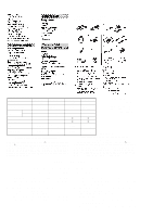
• SUPPLIED ACCESSORIES Check that the following accessories are supplied with your camcorder. • DIFFERENCE TABLE Model DCR-TRV8 Color System NTSC Remote Commander RMT-808 Lens Memory Stick Optical Digital 10 × 120 × - DCR-TRV8E PAL RMT-808 RMT-809 * 10 × 120 ×, 40 × * - DCR-TRV10 NTSC RMT-811 10 × 120 × g DCR-TRV10E PAL RMT-811 RMT-812 * 10 × 120 ×, 40 × * g • Abbreviation AUS: Australian model JE: Tourist model CND: Canadian model CN: Chainese mode HK: Hong Kong model Memory Key - - g g DV IN/OUT IN/OUT * OUT_ONLY IN/OUT IN/OUT * OUT_ONLY AUDIO/VIDEO IN/OUT IN/OUT * OUT_ONLY IN/OUT IN/OUT * OUT_ONLY *: AEP, UK model SAFETY-RELATED COMPONENT WARNING!! COMPONENTS IDENTIFIED BY MARK ! OR DOTTED LINE WITH MARK ! ON THE SCHEMATIC DIAGRAMS AND IN THE PARTS LIST ARE CRITICAL TO SAFE OPERATION. REPLACE THESE COMPONENTS WITH SONY PARTS WHOSE PART NUMBERS APPEAR AS SHOWN IN THIS MANUAL OR IN SUPPLEMENTS PUBLISHED BY SONY. ATTENTION AU COMPOSANT AYANT RAPPORT À LA SÉCURITÉ! LES COMPOSANTS IDENTIFÉS PAR UNE MARQUE ! SUR LES DIAGRAMMES SCHÉMATIQUES ET LA LISTE DES PIÈCES SONT CRITIQUES POUR LA SÉCURITÉ DE FONCTIONNEMENT. NE REMPLACER CES COMPOSANTS QUE PAR DES PIÈSES SONY DONT LES NUMÉROS SONT DONNÉS DANS CE MANUEL OU DANS LES SUPPÉMENTS PUBLIÉS PAR SONY. SAFETY CHECK-OUT After correcting the original service problem, perform the following safety checks before releasing the set to the customer. 1. Check the area of your repair for unsoldered or poorly-soldered 4. Look for parts which, through functioning, show obvious signs connections. Check the entire board surface for solder splashes of deterioration. Point them out to the customer and and bridges. recommend their replacement. 2. Check the interboard wiring to ensure that no wires are 5. Check the B+ voltage to see it is at the values specified. "pinched" or contact high-wattage resistors. 6. Flexible Circuit Board Repairing 3. Look for unauthorized replacement parts, particularly • Keep the temperature of the soldering iron around 270˚C transistors, that were installed during a previous repair. Point during repairing. them out to the customer and recommend their replacement. • Do not touch the soldering iron on the same conductor of the circuit board (within 3 times). • Be careful not to apply force on the conductor when soldering or unsoldering. - 2 -
-
 1
1 -
 2
2 -
 3
3 -
 4
4 -
 5
5 -
 6
6 -
 7
7 -
 8
8 -
9
-
10
-
11
-
12
-
13
-
14
-
15
-
16
-
17
-
18
-
19
-
20
-
21
-
22
-
23
-
24
-
25
-
26
-
27
-
28
-
29
-
30
-
31
-
32
-
33
-
34
-
35
-
36
-
37
-
38
-
39
-
40
-
41
-
42
-
43
-
44
-
45
-
46
-
47
-
48
-
49
-
50
-
51
-
52
-
53
-
54
-
55
-
56
-
57
-
58
-
59
-
60
-
61
-
62
-
63
-
64
-
65
-
66
-
67
-
68
-
69
-
70
-
71
-
72
-
73
-
74
-
75
-
76
-
77
-
78
-
79
-
80
-
81
-
82
-
83
-
84
-
85
-
86
-
87
-
88
-
89
-
90
-
91
-
92
-
93
-
94
-
95
-
96
-
97
-
98
-
99
-
100
-
101
-
102
-
103
-
104
-
105
-
106
-
107
-
108
-
109
-
110
-
111
-
112
-
113
-
114
-
115
-
116
-
117
-
118
-
119
-
120
-
121
-
122
-
123
-
124
-
125
-
126
-
127
-
128
-
129
-
130
-
131
-
132
-
133
-
134
-
135
-
136
-
137
-
138
-
139
-
140
-
141
-
142
-
143
-
144
-
145
-
146
-
147
-
148
-
149
-
150
-
151
-
152
-
153
-
154
-
155
-
156
-
157
-
158
-
159
-
160
-
161
-
162
-
163
-
164
-
165
-
166
-
167
-
168
-
169
-
170
-
171
-
172
-
173
-
174
-
175
-
176
-
177
-
178
-
179
-
180
-
181
-
182
 |
 |
