Sony DCR-TRV10 Service Manual - Page 6
Service Note, Power Supply During Repairs, To Take Out A Cassette When, Not Eject Force Eject
 |
View all Sony DCR-TRV10 manuals
Add to My Manuals
Save this manual to your list of manuals |
Page 6 highlights
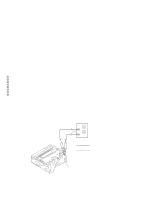
SERVICE NOTE 1. POWER SUPPLY DURING REPAIRS In this unit, about 10 seconds after power is supplied to the battery terminal using the regulated power supply (8.4 V), the power is shut off so that the unit cannot operate. This following two methods are available to prevent this. Take note of which to use during repairs. Method 1. Connect the servicing remote commander RM-95 (J-6082-053-B) to the LANC jack, and set the commander switch to the "ADJ" side. Method 2. Use the DC IN terminal. (Use the AC power adaptor (AC-L10, ACVQ800 etc. )) 2. TO TAKE OUT A CASSETTE WHEN NOT EJECT (FORCE EJECT) 1 Refer to 2-2. to remove the front panel assembly. 2 Refer to 2-3. to remove the cabinet (R) assembly. 3 Refer to 2-3. to remove the battery panel assembly. 4 Refer to 2-4. to remove the viewfinder assembly. 5 Refer to 2-6. to remove DD-123 board. 6 Refer to 2-6. to remove VC-217 board. 7 Refer to 2-7. to remove the mechanism deck. 8 Add +4.5 V from the DC POWER SUPPLY and unload with a pressing the cassette compartment. DC power supply (+4.5 V) : Unloading : Loading Loading motor - 6 -
-
 1
1 -
 2
2 -
 3
3 -
 4
4 -
 5
5 -
 6
6 -
 7
7 -
 8
8 -
 9
9 -
 10
10 -
 11
11 -
 12
12 -
13
-
14
-
15
-
16
-
17
-
18
-
19
-
20
-
21
-
22
-
23
-
24
-
25
-
26
-
27
-
28
-
29
-
30
-
31
-
32
-
33
-
34
-
35
-
36
-
37
-
38
-
39
-
40
-
41
-
42
-
43
-
44
-
45
-
46
-
47
-
48
-
49
-
50
-
51
-
52
-
53
-
54
-
55
-
56
-
57
-
58
-
59
-
60
-
61
-
62
-
63
-
64
-
65
-
66
-
67
-
68
-
69
-
70
-
71
-
72
-
73
-
74
-
75
-
76
-
77
-
78
-
79
-
80
-
81
-
82
-
83
-
84
-
85
-
86
-
87
-
88
-
89
-
90
-
91
-
92
-
93
-
94
-
95
-
96
-
97
-
98
-
99
-
100
-
101
-
102
-
103
-
104
-
105
-
106
-
107
-
108
-
109
-
110
-
111
-
112
-
113
-
114
-
115
-
116
-
117
-
118
-
119
-
120
-
121
-
122
-
123
-
124
-
125
-
126
-
127
-
128
-
129
-
130
-
131
-
132
-
133
-
134
-
135
-
136
-
137
-
138
-
139
-
140
-
141
-
142
-
143
-
144
-
145
-
146
-
147
-
148
-
149
-
150
-
151
-
152
-
153
-
154
-
155
-
156
-
157
-
158
-
159
-
160
-
161
-
162
-
163
-
164
-
165
-
166
-
167
-
168
-
169
-
170
-
171
-
172
-
173
-
174
-
175
-
176
-
177
-
178
-
179
-
180
-
181
-
182
 |
 |
