Sony MZ-NF810CK Service Manual - Page 19
VC1 L, VC1 H, VC2 Lo, VC2 Hi, REG3L1
 |
View all Sony MZ-NF810CK manuals
Add to My Manuals
Save this manual to your list of manuals |
Page 19 highlights
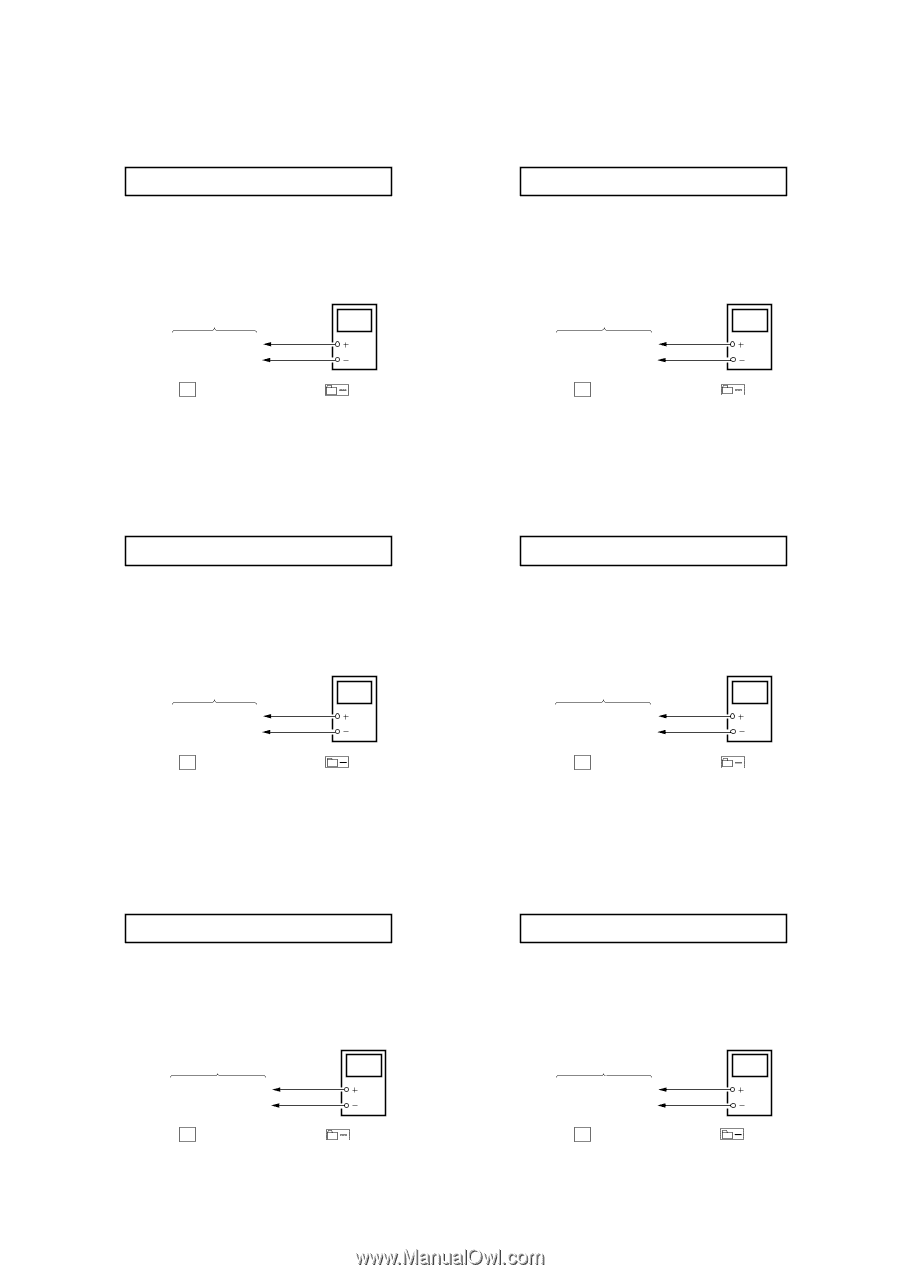
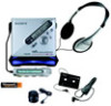
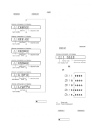
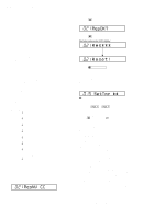
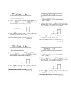
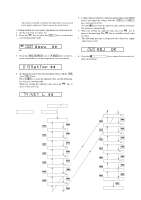
MZ-NF810/NF810CK • Adjustment Method of VC1_LOW (PB) (item number: 741) Remote commander LCD display 741 VC1 L ** **: Adjusted value 1. Connect a digital voltmeter to the TP1928 (VCO1) on the MAIN board, and adjust [VOL +] key (voltage up) or [VOL --] key (voltage down) so that the voltage becomes 2.35 ± 0.05V. digital voltmeter MAIN board TP1928 (VCO1) BATT- (GND) 2. Press the X key on the set or the key on the remote commander to write the adjusted value. Adjustment and Connection Location: MAIN board (see page 22) • Adjustment Method of VC1_HIGH (REC) (item number: 742) Remote commander LCD display 742 VC1 H ** **: Adjusted value 1. Connect a digital voltmeter to the TP1928 (VCO1) on the MAIN board, and adjust [VOL +] key (voltage up) or [VOL --] key (voltage down) so that the voltage becomes 2.75 ± 0.05V. digital voltmeter MAIN board TP1928 (VCO1) BATT- (GND) 2. Press the X key on the set or the key on the remote commander to write the adjusted value. Adjustment and Connection Location: MAIN board (see page 22) • Adjustment Method of VC2_LOW (item number: 743) Remote commander LCD display 743 VC2 Lo ** **: Adjusted value 1. Connect a digital voltmeter to the TP1905 (VCOUT) on the MAIN board, and adjust [VOL +] key (voltage up) or [VOL --] key (voltage down) so that the voltage becomes 2.30 ± 0.01V. digital voltmeter MAIN board TP1905 (VCOUT) BATT- (GND) 2. Press the X key on the set or the key on the remote commander to write the adjusted value. Adjustment and Connection Location: MAIN board (see page 22) • Adjustment Method of VC2_HIGH (item number: 744) Remote commander LCD display 744 VC2 Hi ** **: Adjusted value 1. Connect a digital voltmeter to the TP1905 (VCOUT) on the MAIN board, and adjust [VOL +] key (voltage up) or [VOL --] key (voltage down) so that the voltage becomes 2.55 ± 0.01V. digital voltmeter MAIN board TP1905 (VCOUT) BATT- (GND) 2. Press the X key on the set or the key on the remote commander to write the adjusted value. Adjustment and Connection Location: MAIN board (see page 22) • Adjustment Method of REG1 (item number: 745) Remote commander LCD display 745 REG1 ** **: Adjusted value 1. Connect a digital voltmeter to the TP1909 (REGO1) on the MAIN board, and adjust [VOL +] key (voltage up) or [VOL --] key (voltage down) so that the voltage becomes 2.05 ± 0.01V. digital voltmeter MAIN board TP1909 (REGO1) BATT- (GND) 2. Press the X key on the set or the key on the remote commander to write the adjusted value. Adjustment and Connection Location: MAIN board (see page 22) • Adjustment Method of REG3_LOW1 (H) (item number: 747) Remote commander LCD display 747 REG3L1 ** **: Adjusted value 1. Connect a digital voltmeter to the TP1907 (REGO3) on the MAIN board, and adjust [VOL +] key (voltage up) or [VOL --] key (voltage down) so that the voltage becomes 1.25 ± 0.01V. digital voltmeter MAIN board TP1907 (REGO3) BATT- (GND) 2. Press the X key on the set or the key on the remote commander to write the adjusted value. Adjustment and Connection Location: MAIN board (see page 22) 19
-
 1
1 -
2
-
3
-
4
-
5
-
6
-
7
-
8
-
9
-
10
-
11
-
12
-
13
-
 14
14 -
 15
15 -
 16
16 -
 17
17 -
 18
18 -
 19
19 -
 20
20 -
 21
21 -
 22
22 -
 23
23 -
 24
24 -
25
-
26
-
27
-
28
-
29
-
30
-
31
-
32
-
33
-
34
-
35
-
36
-
37
-
38
-
39
-
40
-
41
-
42
-
43
-
44
-
45
-
46
-
47
-
48
-
49
-
50
-
51
-
52
-
53
-
54
-
55
-
56
-
57
-
58
-
59
-
60
-
61
-
62
-
63
-
64
-
65
-
66
-
67
-
68
 |
 |