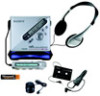
Sony MZ-NF810CK Service Manual - Page 7
Case Lower, MAIN Board, Battery Case
 |
View all Sony MZ-NF810CK manuals
Add to My Manuals
Save this manual to your list of manuals |
Page 7 highlights
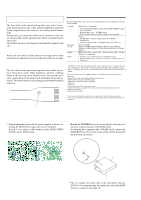
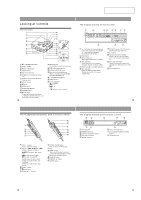
Note: Follow the disassembly procedure in the numerical order given. 3-2. Case (Lower) MZ-NF810/NF810CK 6 two screws (M1.4) 4 two screws (M1.4) 2 claw 7 Remove the case (lower) in the direction of the arrow. 5 screw (M1.4) battery lid 1 Open the battery case lid. 3 Remove the battery case lid. 3-3. MAIN Board, Battery Case 2 Remove the solder of terminal (minus). 1 Remove the solder of terminal (plus). 9 screw (M1.4) 0 screw (M1.4) qs battery terminal board (-) qa battery terminal (+) 3 Remove two solders of the flexible board (over write head). 6 five screws (M1.4) 8 main board qd battery case 4 flexible board (CN871) 7 flexible board (optical pick-up) (CN501) 5 flexible board (motor) (CN701) mechanism deck (MT-MZN710-177) 7
-
 1
1 -
 2
2 -
 3
3 -
 4
4 -
 5
5 -
 6
6 -
 7
7 -
 8
8 -
 9
9 -
 10
10 -
 11
11 -
 12
12 -
13
-
14
-
15
-
16
-
17
-
18
-
19
-
20
-
21
-
22
-
23
-
24
-
25
-
26
-
27
-
28
-
29
-
30
-
31
-
32
-
33
-
34
-
35
-
36
-
37
-
38
-
39
-
40
-
41
-
42
-
43
-
44
-
45
-
46
-
47
-
48
-
49
-
50
-
51
-
52
-
53
-
54
-
55
-
56
-
57
-
58
-
59
-
60
-
61
-
62
-
63
-
64
-
65
-
66
-
67
-
68
 |
 |

7
MZ-NF810/NF810CK
Note:
Follow the disassembly procedure in the numerical order given.
3-2.
Case (Lower)
3-3.
MAIN Board, Battery Case
4
two screws
(M1.4)
6
two screws
(M1.4)
5
screw
(M1.4)
3
Remove the battery
case lid.
battery lid
1
Open the battery
case lid.
2
claw
7
Remove the case (lower) in the
direction of the arrow.
6
five screws
(M1.4)
mechanism deck
(MT-MZN710-177)
7
flexible board (optical pick-up)
(CN501)
5
flexible board (motor)
(CN701)
3
Remove two solders of the
flexible board (over write head).
2
Remove the solder of
terminal (minus).
1
Remove the solder of
terminal (plus).
qd
battery case
qa
battery terminal (+)
9
screw
(M1.4)
0
screw
(M1.4)
qs
battery terminal
board (–)
8
main board
4
flexible board
(CN871)