Sony MZ-NF810CK Service Manual - Page 8
LCD Module, Panel Upper Block, Panel Upper
 |
View all Sony MZ-NF810CK manuals
Add to My Manuals
Save this manual to your list of manuals |
Page 8 highlights
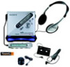
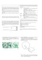
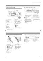
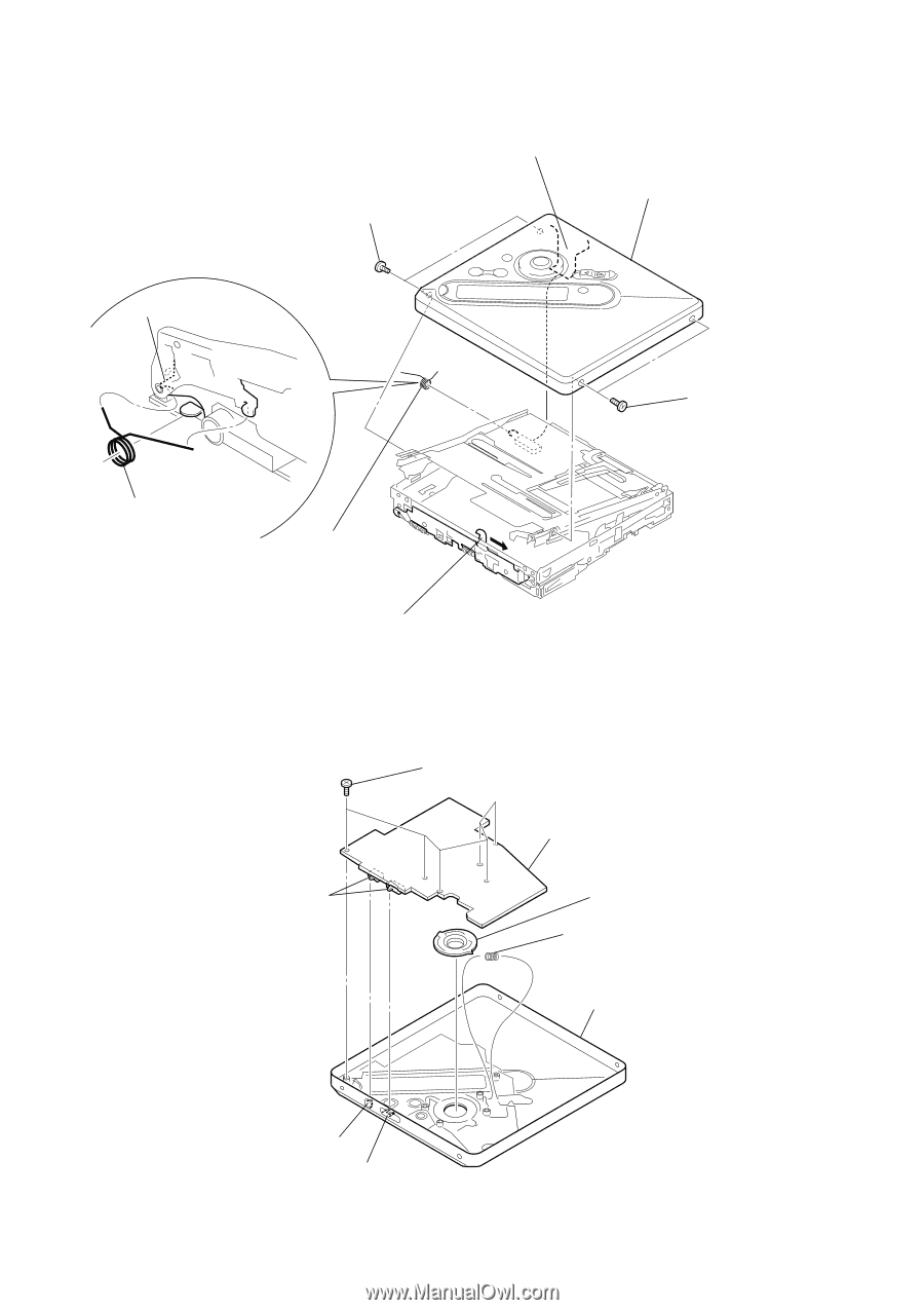
MZ-NF810/NF810CK 3-4. Panel (Upper) Section 3 two screws (M1.4) 1 flexible board (CN871) 5 upper panel section set chassis assy 4 two screws (M1.4) torsion spring (pop up-L) 6 torsion spring (pop up-L) 2 Slide the open slider in the direction of the arrow, and open the upper panel section. 3-5. LCD Module, Panel Upper Block Note: On installation, adjust the position of both switch and knob (hold), knob (t mark). 1 six screws (1.7 × 2.5) 2 LCD module switch 3 button (play) 4 spring (rec) 5 upper panel block button (t mark) knob (hold) 8
-
 1
1 -
2
-
 3
3 -
 4
4 -
 5
5 -
 6
6 -
 7
7 -
 8
8 -
 9
9 -
 10
10 -
 11
11 -
 12
12 -
 13
13 -
14
-
15
-
16
-
17
-
18
-
19
-
20
-
21
-
22
-
23
-
24
-
25
-
26
-
27
-
28
-
29
-
30
-
31
-
32
-
33
-
34
-
35
-
36
-
37
-
38
-
39
-
40
-
41
-
42
-
43
-
44
-
45
-
46
-
47
-
48
-
49
-
50
-
51
-
52
-
53
-
54
-
55
-
56
-
57
-
58
-
59
-
60
-
61
-
62
-
63
-
64
-
65
-
66
-
67
-
68
 |
 |
8
MZ-NF810/NF810CK
3-5.
LCD Module, Panel Upper Block
3-4.
Panel (Upper) Section
1
six screws
(1.7
×
2.5)
2
LCD module
4
spring (rec)
Note:
On installation, adjust the position of
both switch and knob (hold), knob (t mark).
knob (hold)
button (t mark)
3
button (play)
switch
5
upper panel block
3
two screws
(M1.4)
6
torsion spring
(pop up-L)
4
two screws
(M1.4)
2
Slide the open slider in the direction of the arrow,
and open the upper panel section.
set chassis assy
torsion spring (pop up-L)
1
flexible board
(CN871)
5
upper panel section