Sony MZ-NF810CK Service Manual - Page 24
Laser, Lrefpw, HrefPw, WrPwLo, WrPwHi
 |
View all Sony MZ-NF810CK manuals
Add to My Manuals
Save this manual to your list of manuals |
Page 24 highlights
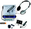
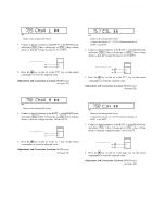
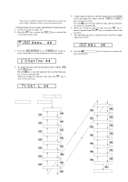
MZ-NF810/NF810CK Laser Power Check Note: If result of measurement of the laser power does not satisfy the specification, either replace the OP (optical pick-up unit) or check whether the laser circuit block is working correctly. When the result of laser power measurement does not satisfy the specification even though the laser circuit block is confirmed to be working correctly, replace the OP (optical pick-up unit). • Connection laser power meter Optical pick-up objective lens • Checking method 1. Select the manual mode of test mode (see page 14), and set the laser power checking mode (item number 010). Remote commander LCD display 010 Laser 2. Press the . T key continuously until the optical pick-up moves to the most inward track. 3. Open the cover and set the laser power meter on the objective lens of the optical pick-up. 4. Press the > t key, and set the laser MO read check mode (item number 011). Remote commander LCD display 011 Lrefpw ** 5. Check that the laser power meter reading is 0.800 ± 0.10 mW. 6. Press the > t key, and set the laser CD read check mode (item number 012). Remote commander LCD display 012 HrefPw ** 7. Check that the laser power meter reading is 0.910 ± 0.11 mW. 8. Press the > t key, and set the laser MO (X2 speed) write check mode (item number 013). Remote commander LCD display 013 WrPwLo ** 9. Check that the laser power meter reading is 4.95 ± 0.59 mW. 10. Press the > t key, and set the laser MO (X4 speed) write check mode (item number 014). Remote commander LCD display 014 WrPwHi ** 11. Check that the laser power meter reading is 5.93 ± 0.71 mW. 12. Press the xCANCEL/CHG key to quit the manual mode, and activate the test mode (display check mode). Overall Adjustment Mode • Configuration of Overall Adjustment Mode Overall adjustment mode (Title display) x key Continuing overall adjustment . key T . key on the remote commander CD overall adjusting > key t > key on the remote commander MO overall adjusting VOL+ key DISPLAY key on the remote commander Electrical offset adjustment [END SEARCH] key [P MODE] key on the remote commander Temperature correction and Power supply adjustment auto item feed • Overall Adjustment Mode (Title Display) Remote commander LCD display 000 Assy** : (Disc mark) At end of power supply adjustment: Outside lit **: Left side = MO overall adjustment information F*: MO overall adjustment completed 1*: Manual adjustment exists (overall adj. not completed) 0*: Not adjusted Right side = CD overall adjustment information *F: CD overall adjustment completed *1: Manual adjustment exists (overall adj. not completed) *0: Not adjusted Note: Adjust the CD first, when performing adjustment. 24
-
 1
1 -
2
-
3
-
4
-
5
-
6
-
7
-
8
-
9
-
10
-
11
-
12
-
13
-
14
-
15
-
16
-
17
-
18
-
 19
19 -
 20
20 -
 21
21 -
 22
22 -
 23
23 -
 24
24 -
 25
25 -
 26
26 -
 27
27 -
 28
28 -
 29
29 -
30
-
31
-
32
-
33
-
34
-
35
-
36
-
37
-
38
-
39
-
40
-
41
-
42
-
43
-
44
-
45
-
46
-
47
-
48
-
49
-
50
-
51
-
52
-
53
-
54
-
55
-
56
-
57
-
58
-
59
-
60
-
61
-
62
-
63
-
64
-
65
-
66
-
67
-
68
 |
 |
