Sony VPL DX15 Operating Instructions - Page 73
surface of this projector and the center of the screen
 |
UPC - 027242762039
View all Sony VPL DX15 manuals
Add to My Manuals
Save this manual to your list of manuals |
Page 73 highlights
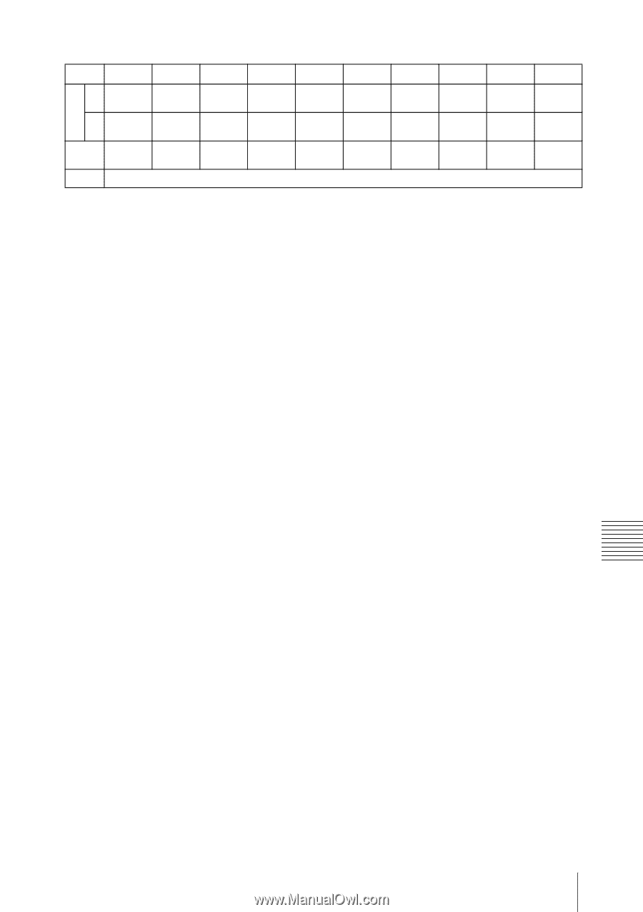
PS 40 a' N 1244 (48 31/32) M 1431 (56 11/32) x b + 240 (b+9 7/16) b Unit: mm (inches) 60 80 100 120 150 180 200 250 300 1842 (72 17/32) 2121 (83 17/32) b + 342 (b+13 7/16) 2440 (96 1/16) 2812 (110 11/16) b + 443 (b+17 7/16) 3038 (119 19/32) 3502 (137 7/8) b + 545 (b+21 7/16) 3635 (143 1/8) 4532 (178 7/16) 4193 5228 (165 1/16) (205 27/32) b + 646 b + 799 (b+25 7/16) (b+31 7/16) Free 5429 (213 23/32) 6264 (246 19/32) b + 951 (b+37 7/16) 6027 (237 9/32) 6954 (273 25/32) b + 1053 (b+41 7/16) 7521 (296 3/32) 8680 (341 3/4) b + 1307 (b+51 7/16) 9016 (354 15/16) 10406 (409 11/16) b + 1561 (b+61 7/16) a'(N) = {(PS × 18.46/0.6299)-34.7} × 1.02+84 a'(M) = {(PS × 22.19/0.6299)-34.6} × 0.98+84 x = PS/0.6299 × 3.2+36.7 The alphabetical letters in the charts and calculation methods indicate the following. PS: projected image size measured diagonally (inches) a': distance between the hole (front) for mounting a projector suspension support on bottom surface of this projector and the center of the screen b: distance between the projector suspension support mounting surface on bottom of this projector and the ceiling x: distance between the center of the screen and the ceiling N: minimum M: maximum Others Installing the Projector and Installation Diagram 73
-
 1
1 -
2
-
3
-
4
-
5
-
6
-
7
-
8
-
9
-
10
-
11
-
12
-
13
-
14
-
15
-
16
-
17
-
18
-
19
-
20
-
21
-
22
-
23
-
24
-
25
-
26
-
27
-
28
-
29
-
30
-
31
-
32
-
33
-
34
-
35
-
36
-
37
-
38
-
39
-
40
-
41
-
42
-
43
-
44
-
45
-
46
-
47
-
48
-
49
-
50
-
51
-
52
-
53
-
54
-
55
-
56
-
57
-
58
-
59
-
60
-
61
-
62
-
63
-
64
-
65
-
66
-
67
-
 68
68 -
 69
69 -
 70
70 -
 71
71 -
 72
72 -
 73
73 -
 74
74 -
 75
75 -
 76
76 -
 77
77 -
 78
78 -
79
 |
 |