ViewSonic PJD7583wi PJD7383, PJD7383I, PJD7583W, PJD7583WI User Guide (English - Page 11
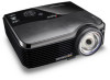
Projector exterior view
 |
UPC - 766907511123
View all ViewSonic PJD7583wi manuals
Add to My Manuals
Save this manual to your list of manuals |
Page 11 highlights
Projector exterior view Front/upper side 1 2 3 4 5 Rear/lower side 9 10 11 12 13 14 15 16 24 25 Warning 1. 2. 3. 4. 5. 6. 7. 8. 9. 10. 6 11. 7 12. 8 13. 14. 15. 16. 17. 17 18 19 20 21 22 18. DC 12V OUT 23 19. 20. 21. 22. 24 23. 24. 25. External control panel (See "Projector" on page 8 for details.) Lamp cover Vent (heated air exhaust) Quick-release button Lens cover Front IR remote sensor Focus ring Projection lens Kensington anti-theft lock slot AC power cord inlet Rear IR remote sensor RJ45 LAN input port Mini B USB port Type A USB port RS-232 control port RGB signal output socket RGB (PC)/Component video (YPbPr/YCbCr) signal input socket-1/2 Video input socket/ S-Video input socket Audio signal input socket (L/R) Audio signal input socket Audio signal output socket Microphone input socket Connects a microphone with a 3.5 mm mini jack cable or wireless module. Security bar Connects a commercially available theft prevention cable. 12V DC output terminal Used to trigger external devices such as an electric screen or light control, etc. Consult your dealer for how to connect these devices. Rear adjuster foot Quick-release foot • THIS APPARATUS MUST BE EARTHED. • When installing the unit, incorporate a readily accessible disconnect device in the fixed wiring, or connect the power plug to an easily accessible socket-outlet near the unit. If a fault should occur during operation of the unit, operate the disconnect device to switch the power supply off, or disconnect the power plug. Introduction 7
-
 1
1 -
2
-
3
-
4
-
5
-
 6
6 -
 7
7 -
 8
8 -
 9
9 -
 10
10 -
 11
11 -
 12
12 -
 13
13 -
 14
14 -
 15
15 -
 16
16 -
17
-
18
-
19
-
20
-
21
-
22
-
23
-
24
-
25
-
26
-
27
-
28
-
29
-
30
-
31
-
32
-
33
-
34
-
35
-
36
-
37
-
38
-
39
-
40
-
41
-
42
-
43
-
44
-
45
-
46
-
47
-
48
-
49
-
50
-
51
-
52
-
53
-
54
-
55
-
56
-
57
-
58
-
59
-
60
-
61
-
62
-
63
-
64
-
65
-
66
-
67
-
68
-
69
-
70
-
71
-
72
-
73
-
74
-
75
-
76
-
77
-
78
-
79
-
80
-
81
-
82
-
83
-
84
-
85
-
86
-
87
-
88
-
89
-
90
-
91
-
92
-
93
-
94
-
95
 |
 |
