Xerox 3450B Service Manual - Page 108
Service Parts Disassembly, Raise the cover slightly, so the boss
 |
UPC - 095205120011
View all Xerox 3450B manuals
Add to My Manuals
Save this manual to your list of manuals |
Page 108 highlights
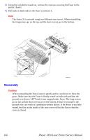
3. Close the Tray 1 cover about half way then push outward on the top of the left slot track that the link pin rides in and disconnect the Tray Link from the left cover slot. Next, flex the top of the right track and release right Tray Link. 1 2 3 1. Tray Link 2. Link Pin s3450-004 3. Slot Track 4. Raise the cover slightly, so the boss, located behind the hinge on the left side of the cover, clears the hinge pin mount, and slide the cover to the right and pull out to remove it from the printer. 1 2 1. Tray 1 Cover 2. Hinge s3450-006 Service Parts Disassembly 8-11
-
 1
1 -
2
-
3
-
4
-
5
-
6
-
7
-
8
-
9
-
10
-
11
-
12
-
13
-
14
-
15
-
16
-
17
-
18
-
19
-
20
-
21
-
22
-
23
-
24
-
25
-
26
-
27
-
28
-
29
-
30
-
31
-
32
-
33
-
34
-
35
-
36
-
37
-
38
-
39
-
40
-
41
-
42
-
43
-
44
-
45
-
46
-
47
-
48
-
49
-
50
-
51
-
52
-
53
-
54
-
55
-
56
-
57
-
58
-
59
-
60
-
61
-
62
-
63
-
64
-
65
-
66
-
67
-
68
-
69
-
70
-
71
-
72
-
73
-
74
-
75
-
76
-
77
-
78
-
79
-
80
-
81
-
82
-
83
-
84
-
85
-
86
-
87
-
88
-
89
-
90
-
91
-
92
-
93
-
94
-
95
-
96
-
97
-
98
-
99
-
100
-
101
-
102
-
 103
103 -
 104
104 -
 105
105 -
 106
106 -
 107
107 -
 108
108 -
 109
109 -
 110
110 -
 111
111 -
 112
112 -
 113
113 -
114
-
115
-
116
-
117
-
118
-
119
-
120
-
121
-
122
-
123
-
124
-
125
-
126
-
127
-
128
-
129
-
130
-
131
-
132
-
133
-
134
-
135
-
136
-
137
-
138
-
139
-
140
-
141
-
142
-
143
-
144
-
145
-
146
-
147
-
148
-
149
-
150
-
151
-
152
-
153
-
154
-
155
-
156
-
157
-
158
-
159
-
160
-
161
-
162
-
163
-
164
-
165
-
166
-
167
-
168
-
169
-
170
-
171
-
172
-
173
-
174
-
175
-
176
-
177
-
178
-
179
-
180
 |
 |

Service Parts Disassembly
8-11
3.
Close the Tray 1 cover about half way then push outward on the top of the left
slot track that the link pin rides in and disconnect the Tray Link from the left
cover slot. Next, flex the top of the right track and release right Tray Link.
4.
Raise the cover slightly, so the boss, located behind the hinge on the left side of
the cover, clears the hinge pin mount, and slide the cover to the right and pull out
to remove it from the printer.
1.
Tray Link
2.
Link Pin
3.
Slot Track
1.
Tray 1 Cover
2.
Hinge
1
2
3
s3450-004
1
2
s3450-006