Xerox 3450B Service Manual - Page 110
Tray 1 Lift Plate (PL 9.1.3
 |
UPC - 095205120011
View all Xerox 3450B manuals
Add to My Manuals
Save this manual to your list of manuals |
Page 110 highlights
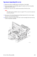
2. Remove the Tray 1 Cover Assembly (page 8-10). 3. Remove the Top Cover Assembly (page 8-9). 4. Disconnect the Tray 1 Lift Plate Links from the Tray 1 Lift Plate by pulling outward on the end of the Link arms where they connect to the lift plate. 5. Rotate each Link to align the key with the slot in the frame mounting hole and remove the Links. 6. Remove the two screws securing the Front Cover to the printer, unlatch the two retaining hooks on each side, and remove the Front Cover. s3450-042 Tray 1 Lift Plate (PL 9.1.3) 1. Remove the Front (Inner) Cover (page 8-12). 2. Disconnect the 2 Bias Springs from the metal frame. Note In some cases, the Bias Springs will slip off of the plastic mounting arms on the Lift Plate easily and they can be disconnected just as readily that way. However, there is less chance of damage when removing the springs from the metal frame. 3. Remove the Tray 1 Lift Plate. Service Parts Disassembly 8-13
-
 1
1 -
2
-
3
-
4
-
5
-
6
-
7
-
8
-
9
-
10
-
11
-
12
-
13
-
14
-
15
-
16
-
17
-
18
-
19
-
20
-
21
-
22
-
23
-
24
-
25
-
26
-
27
-
28
-
29
-
30
-
31
-
32
-
33
-
34
-
35
-
36
-
37
-
38
-
39
-
40
-
41
-
42
-
43
-
44
-
45
-
46
-
47
-
48
-
49
-
50
-
51
-
52
-
53
-
54
-
55
-
56
-
57
-
58
-
59
-
60
-
61
-
62
-
63
-
64
-
65
-
66
-
67
-
68
-
69
-
70
-
71
-
72
-
73
-
74
-
75
-
76
-
77
-
78
-
79
-
80
-
81
-
82
-
83
-
84
-
85
-
86
-
87
-
88
-
89
-
90
-
91
-
92
-
93
-
94
-
95
-
96
-
97
-
98
-
99
-
100
-
101
-
102
-
103
-
104
-
 105
105 -
 106
106 -
 107
107 -
 108
108 -
 109
109 -
 110
110 -
 111
111 -
 112
112 -
 113
113 -
 114
114 -
 115
115 -
116
-
117
-
118
-
119
-
120
-
121
-
122
-
123
-
124
-
125
-
126
-
127
-
128
-
129
-
130
-
131
-
132
-
133
-
134
-
135
-
136
-
137
-
138
-
139
-
140
-
141
-
142
-
143
-
144
-
145
-
146
-
147
-
148
-
149
-
150
-
151
-
152
-
153
-
154
-
155
-
156
-
157
-
158
-
159
-
160
-
161
-
162
-
163
-
164
-
165
-
166
-
167
-
168
-
169
-
170
-
171
-
172
-
173
-
174
-
175
-
176
-
177
-
178
-
179
-
180
 |
 |
