Zenith P50W26B Operating Guide - Page 22
External Control Device Setup
 |
View all Zenith P50W26B manuals
Add to My Manuals
Save this manual to your list of manuals |
Page 22 highlights
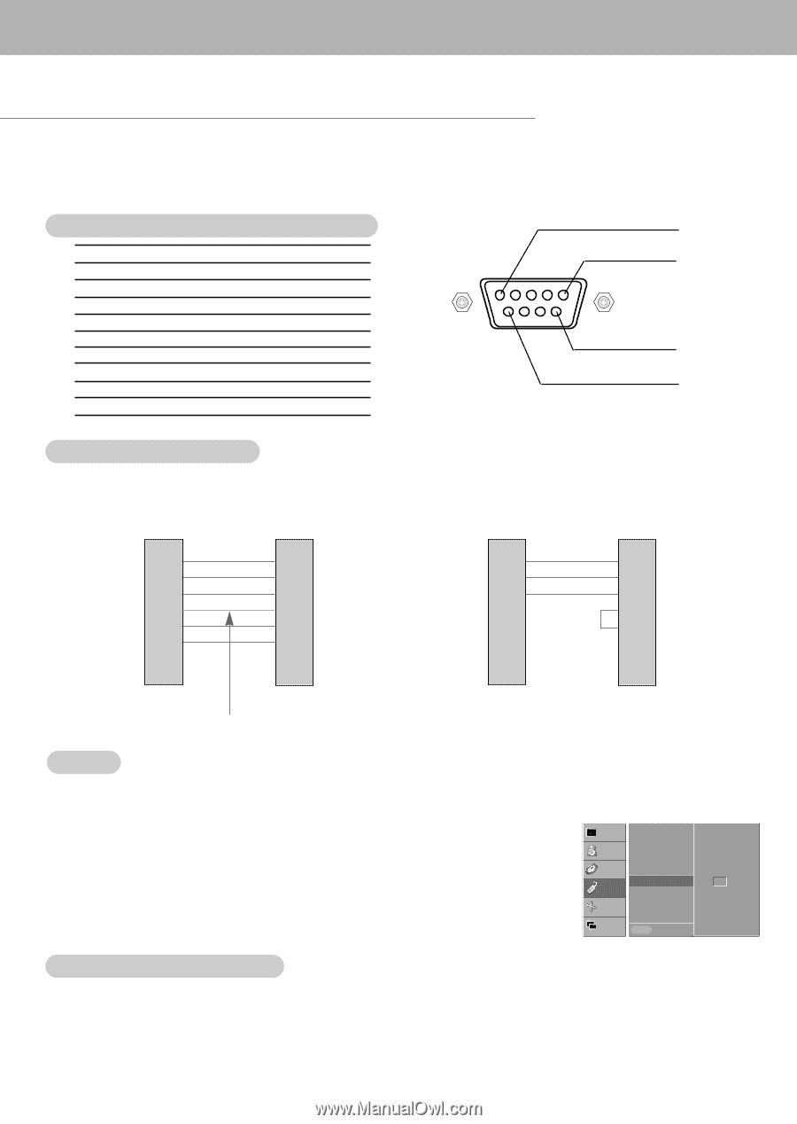
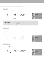
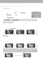
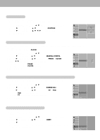
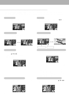
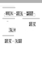
External Control Device Setup - Connect the RS-232C input jack to an external control device (such as a computer or an A/V control system) and control the Monitor's functions externally. - Connect the serial port of the control device to the RS-232C jack on the Monitor back panel. - RS-232C connection cables are not supplied with the Monitor. Type of connector; D-Sub 9-pin male 1 No. Pin name 5 1 No connection 2 RXD (Receive data) 3 TXD (Transmit data) 4 DTR (DTE side ready) 5 GND 6 DSR (DCE side ready) 9 7 RTS (Ready to send) 8 CTS (Clear to send) 6 9 No Connection RS-232C configurations 7-wire configuration (Standard RS-232C cable) PC PDP RXD 2 TXD 3 GND 5 DTR 4 DSR 6 RTS 7 CTS 8 3 TXD 2 RXD 5 GND 6 DSR 4 DTR 8 CTS 7 RTS 3-wire configuration (Not standard) PC PDP RXD 2 TXD 3 GND 5 DTR 4 DSR 6 RTS 7 CTS 8 3 TXD 2 RXD 5 GND 4 DTR 6 DSR 7 RTS 8 CTS D-Sub 9 D-Sub 9 Control line D-Sub 9 Set ID - Use this function to specify a monitor ID number. - Refer to 'Real Data Mapping 1'. See page 24. 1. Press the MENU button and then use D / E button to select the SPECIAL menu. 2. Press the G button and then use D / E button to select SET ID. 3. Press the G button and then use F / G button to adjust SET ID to choose the desired monitor ID number. • The adjustment range of SET ID is 1 ~ 99. D-Sub 9 VIDEO AUDIO TIME LANGUAGE KEY LOCK ORBITER WHITE WASH SET ID SPECIAL G 1 SCREEN TWIN MENU PREV. Communication Parameters • Baud rate : 115200 bps (UART) • Data length : 8 bits • Parity : None • Stop bit : 1 bit • Communication code : ASCII code 22
-
 1
1 -
2
-
3
-
4
-
5
-
6
-
7
-
8
-
9
-
10
-
11
-
12
-
13
-
14
-
15
-
16
-
 17
17 -
 18
18 -
 19
19 -
 20
20 -
 21
21 -
 22
22 -
 23
23 -
 24
24 -
 25
25 -
 26
26 -
 27
27 -
28
-
29
-
30
-
31
-
32
 |
 |