Zenith Z50PX2D Operating Guide - Page 42
External Control Device Setup
 |
UPC - 044642702182
View all Zenith Z50PX2D manuals
Add to My Manuals
Save this manual to your list of manuals |
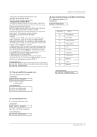
Page 42 highlights
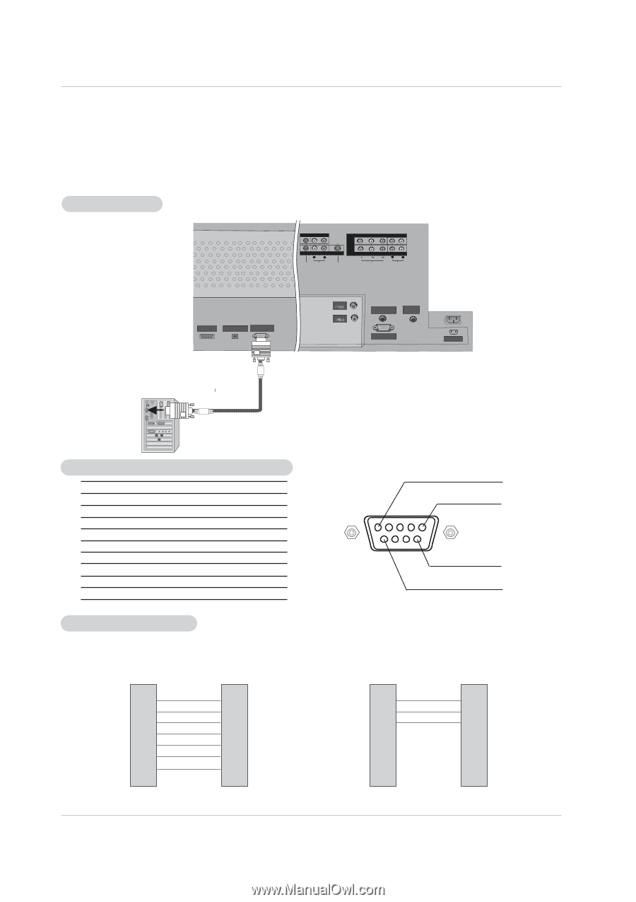
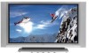
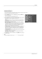
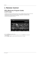
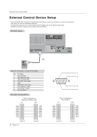
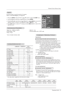
External Control Device Setup External Control Device Setup - Connect the RS-232C input jack to an external control device (such as a computer or an A/V control system) and control the Monitor's functions externally. - Connect the serial port of the control device to the RS-232C jack on the Monitor back panel. - RS-232C connection cables are not supplied with the Monitor. RS-232C Setup MONITOR OUTPUT (MONO) A/V INPUT L R VIDEO AUDIO DVD /DTV INPUT S-VIDEO COMPONENT INPUT 2 COMPONENT INPUT 1 L R VIDEO AUDIO HDMI /DVI (VIDEO) INPUT DIGITAL AUDIO OPTICAL OUTPUT RS-232C INPUT (CONTROL/SERVICE) ANTENNA CABLE RGB/DVI AUDIO INPUT REMOTE CONTROL RGB INPUT AC INPUT PC Type of Connector; D-Sub 9-Pin Male No. Pin Name 1 No connection 2 RXD (Receive data) 3 TXD (Transmit data) 4 DTR (DTE side ready) 5 GND 6 DSR (DCE side ready) 7 RTS (Ready to send) 8 CTS (Clear to send) 9 No Connection RS-232C Configurations 7-Wire Configurations (Standard RS-232C cable) PC PDP RXD 2 TXD 3 GND 5 DTR 4 DSR 6 RTS 7 CTS 8 3 TXD 2 RXD 5 GND 6 DSR 4 DTR 8 CTS 7 RTS D-Sub 9 42 Plasma TV D-Sub 9 1 5 9 6 3-Wire Configurations (Not standard) PC PDP RXD 2 TXD 3 GND 5 DTR 4 DSR 6 RTS 7 CTS 8 3 TXD 2 RXD 5 GND 4 DTR 6 DSR 7 RTS 8 CTS D-Sub 9 D-Sub 9
-
 1
1 -
2
-
3
-
4
-
5
-
6
-
7
-
8
-
9
-
10
-
11
-
12
-
13
-
14
-
15
-
16
-
17
-
18
-
19
-
20
-
21
-
22
-
23
-
24
-
25
-
26
-
27
-
28
-
29
-
30
-
31
-
32
-
33
-
34
-
35
-
36
-
 37
37 -
 38
38 -
 39
39 -
 40
40 -
 41
41 -
 42
42 -
 43
43 -
 44
44 -
 45
45 -
 46
46 -
 47
47 -
48
-
49
-
50
-
51
-
52
-
53
-
54
-
55
-
56
-
57
-
58
-
59
-
60
 |
 |