Zenith Z50PX2D Operating Guide - Page 8
Connection Options - power supply
 |
UPC - 044642702182
View all Zenith Z50PX2D manuals
Add to My Manuals
Save this manual to your list of manuals |
Page 8 highlights
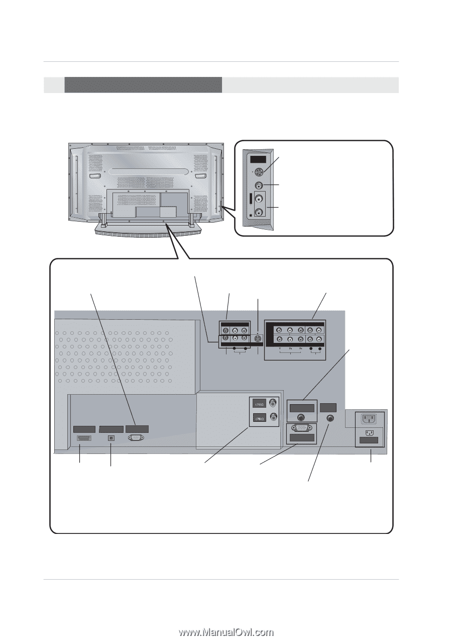
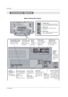
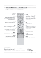
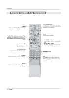
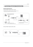
Introduction Connection Options Back Connection Panel S-VIDEO R AUDIO L / MONO VIDEO FRONT A/V INPUT S-VIDEO Input A connection available to provide better picture quality than the video input. VIDEO Input Connects the video signal from a video device. AUDIO Input Use to connect to hear stereo sound from an external device. RS-232C INPUT (CONTROL/SERVICE) PORT Connect to the RS232C port on a PC. Audio/Video Input Connect audio/video output from an external device to these jacks. Monitor Output Connect a second TV or Monitor. S-Video Input Connect S-Video out from an S-VIDEO device to the SVIDEO input. DVD/DTV Input (Component 1-2) Connect a component video/audio device to these jacks. HDMI /DVI (VIDEO) INPUT DIGITAL AUDIO OPTICAL OUTPUT RS-232C INPUT (CONTROL/SERVICE) MONITOR OUTPUT (MONO) A/V INPUT L R VIDEO AUDIO DVD /DTV INPUT S-VIDEO COMPONENT INPUT 2 COMPONENT INPUT 1 L R VIDEO AUDIO ANTENNA CABLE RGB/DVI AUDIO INPUT REMOTE CONTROL RGB/DVI AUDIO INPUT In RGB input or DVI input, this port supplies Analog audio. RGB INPUT AC INPUT HDMI/DVI Digital Audio Output (VIDEO)INPUT Connect digital audio connect a from various types of DVI(Video) sig- equipment. nal to HDMI/DVI. Note: In standby mode, this port will not work. Antenna Input Connect over-theair signals to this jack. CABLE Input Connect cable signals to this jack. RGB INPUT Power Cord Socket Connect the monitor This TV operates on output connector from a PC to the appropriate input port. an AC power. The Remote voltage is indicated on Control Port the Specifications Connect your page. Never attempt wired remote to operate the TV on control here. DC power. 8 Plasma TV
-
 1
1 -
2
-
 3
3 -
 4
4 -
 5
5 -
 6
6 -
 7
7 -
 8
8 -
 9
9 -
 10
10 -
 11
11 -
 12
12 -
 13
13 -
14
-
15
-
16
-
17
-
18
-
19
-
20
-
21
-
22
-
23
-
24
-
25
-
26
-
27
-
28
-
29
-
30
-
31
-
32
-
33
-
34
-
35
-
36
-
37
-
38
-
39
-
40
-
41
-
42
-
43
-
44
-
45
-
46
-
47
-
48
-
49
-
50
-
51
-
52
-
53
-
54
-
55
-
56
-
57
-
58
-
59
-
60
 |
 |