eMachines D620 Service Guide - Page 39
Disassembly Process, Main Screw List
 |
View all eMachines D620 manuals
Add to My Manuals
Save this manual to your list of manuals |
Page 39 highlights
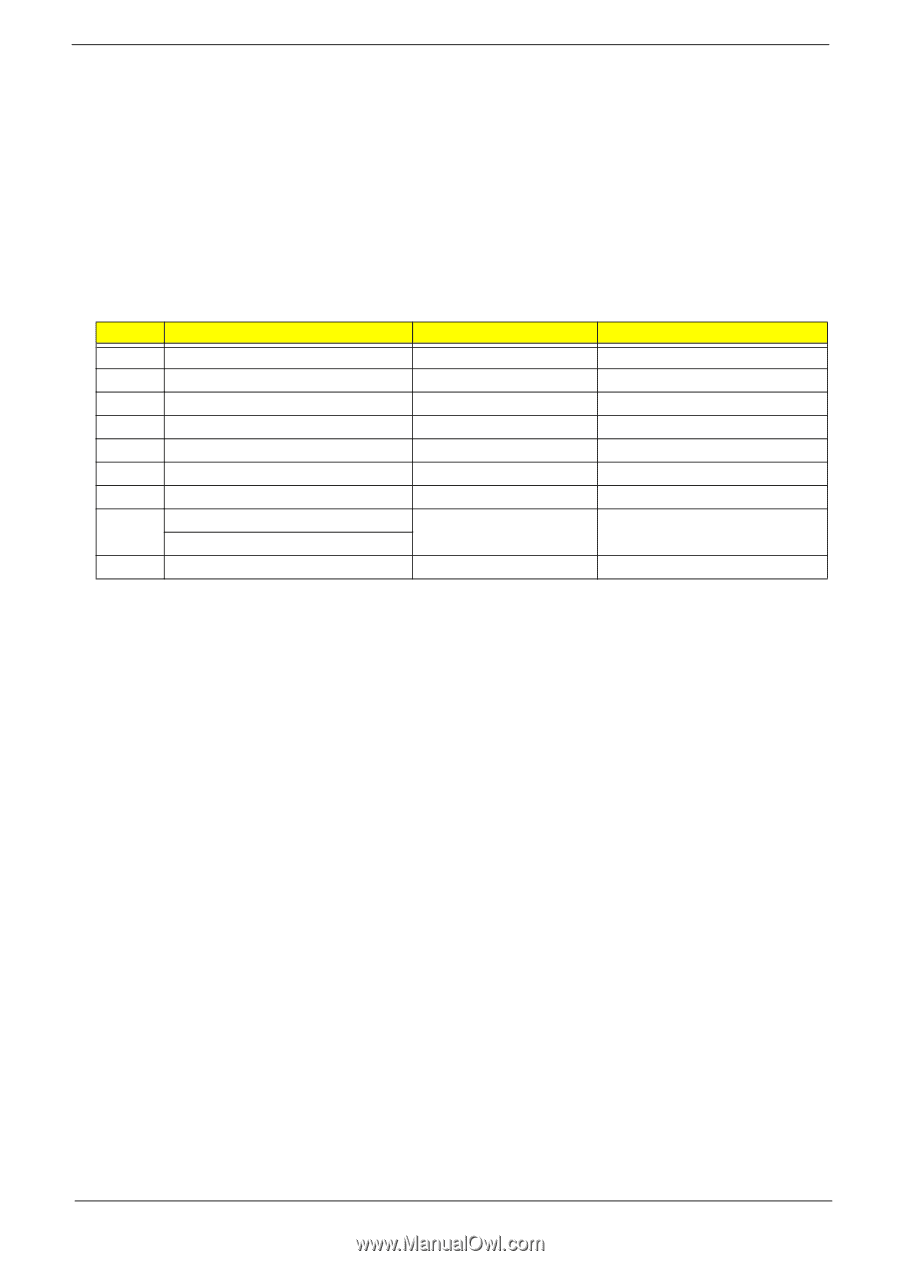
Disassembly Process The disassembly process is divided into the following stages: • External module disassembly • Main unit disassembly • LCD module disassembly The flowcharts provided in the succeeding disassembly sections illustrate the entire disassembly sequence. Observe the order of the sequence to avoid damage to any of the hardware components. For example, if you want to remove the mainboard, you must first remove the keyboard, then disassemble the inside assembly frame in that order. Main Screw List Item A B C D E F G H I Screw M2 x L4 M2 x L18 M2 x L3 M3 x L4 M2.5 x L6 M2 x L2.5 M2 x L3 M2.5 x L5 (torque 1.6) M2.5 x L5 (torque 3.0) M2.5 x L5 (torque 2.5) Color Black/Silver Black Silver Silver Black Silver Silver Black Black Part No. 86.9A552.4R0 86.00G64.720 86.9A552.3R0 86.9A524.4R0 86.00E33.736 86.00F22.722 86.00C07.220 86.00F87.735 86.00F00.735 Chapter 3 49
-
 1
1 -
2
-
3
-
4
-
5
-
6
-
7
-
8
-
9
-
10
-
11
-
12
-
13
-
14
-
15
-
16
-
17
-
18
-
19
-
20
-
21
-
22
-
23
-
24
-
25
-
26
-
27
-
28
-
29
-
30
-
31
-
32
-
33
-
 34
34 -
 35
35 -
 36
36 -
 37
37 -
 38
38 -
 39
39 -
 40
40 -
 41
41 -
 42
42 -
 43
43 -
 44
44 -
45
-
46
-
47
-
48
-
49
-
50
-
51
-
52
-
53
-
54
-
55
-
56
-
57
-
58
-
59
-
60
-
61
-
62
-
63
-
64
-
65
-
66
-
67
-
68
-
69
-
70
-
71
-
72
-
73
-
74
-
75
-
76
-
77
-
78
-
79
-
80
-
81
-
82
-
83
-
84
-
85
-
86
-
87
-
88
-
89
-
90
-
91
-
92
-
93
-
94
-
95
-
96
-
97
-
98
-
99
-
100
-
101
-
102
-
103
-
104
-
105
-
106
-
107
-
108
-
109
-
110
-
111
-
112
-
113
-
114
-
115
-
116
-
117
-
118
 |
 |