eMachines D620 Service Guide - Page 72
Removing the LCD Module Hinges
 |
View all eMachines D620 manuals
Add to My Manuals
Save this manual to your list of manuals |
Page 72 highlights
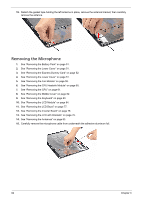
13. Remove the eight screws (C) securing the left and right LCD brackets to remove the brackets. Step 1~8 Size (Quantity) M2 x L3 (8) Color Silver Removing the LCD Module Hinges 1. See "Removing the Battery Pack" on page 51. 2. See "Removing the Lower Cover" on page 51. 3. See "Removing the Lower Cover" on page 51. 4. See "Removing the Fan Module" on page 59. 5. See "Removing the CPU Heatsink Module" on page 60. 6. See "Removing the CPU" on page 61. 7. See "Removing the Middle Cover" on page 62. 8. See "Removing the Keyboard" on page 63. 9. See "Removing the LCD Module" on page 64. 10. See "Removing the LCD Bezel" on page 77. 11. See "Removing the Inverter Board" on page 78. 12. See "Removing the LCD with Brackets" on page 79. 13. See "Removing the LCD Brackets" on page 81. 14. Remove the two screws (I) securing the left and right LCD module hinges. Torque 1.6 kgf-cm Step 1~2 Size (Quantity) M2.5 x L5 (2) Color Black Torque 2.5 kgf-cm 82 Chapter 3
-
 1
1 -
2
-
3
-
4
-
5
-
6
-
7
-
8
-
9
-
10
-
11
-
12
-
13
-
14
-
15
-
16
-
17
-
18
-
19
-
20
-
21
-
22
-
23
-
24
-
25
-
26
-
27
-
28
-
29
-
30
-
31
-
32
-
33
-
34
-
35
-
36
-
37
-
38
-
39
-
40
-
41
-
42
-
43
-
44
-
45
-
46
-
47
-
48
-
49
-
50
-
51
-
52
-
53
-
54
-
55
-
56
-
57
-
58
-
59
-
60
-
61
-
62
-
63
-
64
-
65
-
66
-
 67
67 -
 68
68 -
 69
69 -
 70
70 -
 71
71 -
 72
72 -
 73
73 -
 74
74 -
 75
75 -
 76
76 -
 77
77 -
78
-
79
-
80
-
81
-
82
-
83
-
84
-
85
-
86
-
87
-
88
-
89
-
90
-
91
-
92
-
93
-
94
-
95
-
96
-
97
-
98
-
99
-
100
-
101
-
102
-
103
-
104
-
105
-
106
-
107
-
108
-
109
-
110
-
111
-
112
-
113
-
114
-
115
-
116
-
117
-
118
 |
 |
