eMachines EL1852 eMachines EL1852 Service Guide
eMachines EL1852 Manual
 |
View all eMachines EL1852 manuals
Add to My Manuals
Save this manual to your list of manuals |
eMachines EL1852 manual content summary:
- eMachines EL1852 | eMachines EL1852 Service Guide - Page 1
eMachines EL1852 Service Guide PRINTED IN TAIWAN - eMachines EL1852 | eMachines EL1852 Service Guide - Page 2
Revision History Refer to the table below for changes made on this version of the EL1852 Desktop Computer Service Guide. Date Chapter Updates ii EL1852 Service Guide - eMachines EL1852 | eMachines EL1852 Service Guide - Page 3
system, or translated into any language or computer language, in any form or by any means, electronic, mechanical, magnetic, optical, chemical, manual or otherwise, without the prior written permission of Acer Incorporated. Disclaimer The information in this guide is subject to change without notice - eMachines EL1852 | eMachines EL1852 Service Guide - Page 4
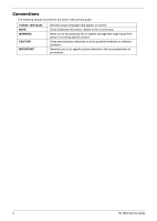
The following textual conventions are used in this service guide. SCREEN MESSAGES NOTE WARNING CAUTION IMPORTANT Denotes actual measures to avoid possible hardware or software problems. Reminds you to do specific actions relevant to the accomplishment of procedures. iv EL1852 Service Guide - eMachines EL1852 | eMachines EL1852 Service Guide - Page 5
, your regional office MAY have decided to extend the functionality of a machine (e.g. add-on card, modem, or extra memory capability). These LOCALIZED FEATURES will NOT be covered in this generic service guide. In such cases, please contact your regional offices or the responsible personnel - eMachines EL1852 | eMachines EL1852 Service Guide - Page 6
vi EL1852 Service Guide - eMachines EL1852 | eMachines EL1852 Service Guide - Page 7
Boards 33 Removing the Memory Modules 35 Removing the Power Supply Unit 35 Removing the Front I/O and Card Reader Assembly 37 Removing the Mainboard 40 Hardware Diagnostic Procedure 41 System Check Procedures 41 Checkpoints 42 POST Error Indicators 46 BIOS Recovery 58 BIOS Update 59 - eMachines EL1852 | eMachines EL1852 Service Guide - Page 8
Table of Contents Memory 87 Hard Disk Drive 88 Optical Disc Drive 88 Card Reader 89 Gigabit Ethernet 89 Audio 89 Power Supply Unit 89 Power Management 90 Index ...91 viii EL1852 Service Guide - eMachines EL1852 | eMachines EL1852 Service Guide - Page 9
• WLAN option: 802.11 b/g/n wireless network adapter • One HDD bay suppporting 3.5-inch 25.4 mm SATA HDDs • Support SATA HDD in 160 - 1500 GB capacities • One ODD bay supporting 5.25-inch standard SATA ODD • Supports DVD-R/RW drive or DVD-Super Multi double-layer drive EL1852 Service Guide 1 - eMachines EL1852 | eMachines EL1852 Service Guide - Page 10
Component Card reader (optional) Power supply Antivirus software System BIOS Power management Audio Item Audio codec Audio jacks Description • Multi-in-1 card reader • The following memory cards are supported: - Memory Stick (MS) - xD-Picture Card (xD) - Secure Digital (SD), MultiMediaCard (MMC), - eMachines EL1852 | eMachines EL1852 Service Guide - Page 11
Kg. microATX (µATX) 244 × 200 mm Environmental Requirements Aspect Operating temperature Operating humidity Description 5 to 35 °C (41 to 95 °F) 15% to 80% RH non-condensing EL1852 Service Guide 3 - eMachines EL1852 | eMachines EL1852 Service Guide - Page 12
and tables in this section illustrate the physical outlook of the computer. Front View No. Component 1 Optical drive eject button 2 Optical drive cover 3 Power button/indicator 4 Microphone-in jack 5 Headphone jack 6 Multi-in-1 card reader 7 USB 2.0 ports 4 EL1852 Service Guide - eMachines EL1852 | eMachines EL1852 Service Guide - Page 13
. Component 1 Line-in jack 2 LAN connector 3 Key lock 4 Kensington lock 5 Power connector 6 Fan aperture 7 PS/2 keyboard connector 8 PS/2 mouse connector 9 Monitor port 10 USB 2.0 items made possible with the installation of an expansion card option. EL1852 Service Guide 5 - eMachines EL1852 | eMachines EL1852 Service Guide - Page 14
6 EL1852 Service Guide - eMachines EL1852 | eMachines EL1852 Service Guide - Page 15
sequence • Configuring the power management modes • Setting up memory called CMOS RAM. This memory area is not part of the system RAM, which allows configuration data to be retained when power the system cannot retain configuration values in CMOS. Replace the RTC battery with a new one. NOTE For - eMachines EL1852 | eMachines EL1852 Service Guide - Page 16
you to change the values for the option. Use the Up/Down/Left/Right arrow keys to scroll through the items in the submenu 8 EL1358 Service Guide - eMachines EL1852 | eMachines EL1852 Service Guide - Page 17
. These include: • Product Information • PC Health Status • Standard CMOS Features • Integrated Peripherals • Save & Exit Setup • Power Management Setup • Exit Without Saving NOTES • displayed may not be the same as those in your computer. • In the descriptive tables following each of the - eMachines EL1852 | eMachines EL1852 Service Guide - Page 18
are not user-configurable. Parameter Processor Type Processor Speed System Memory Product Name System Serial Number System BIOS Version BIOS Release installed on the system Size of system memory detected during boot-up Official model name of the computer. System serial number. Current system BIOS - eMachines EL1852 | eMachines EL1852 Service Guide - Page 19
supports two SATA channels, each channel allows one SATA device to be installed. Press Enter to display the individual configuration screen of installed SATA drive(s). Determines whether the system will stop for an error during the POST. All, But Keyboard No Errors All Errors EL1358 Service Guide - eMachines EL1852 | eMachines EL1852 Service Guide - Page 20
Setup Utility attempts to boot the operating system in this order. By default, the computer searches for boot devices in the following order: • Hard disk • Optical drive (CD/DVD) • Removable device • Network boot (LAN) Press Enter to specify the boot device priority sequence for the installed hard - eMachines EL1852 | eMachines EL1852 Service Guide - Page 21
that support the Physical Address Extension method. Select the amount of system memory used by the internal graphics device. This setting is only available for WinXp. Value Enabled Disabled Enabled Disabled Enabled Disabled Enabled Disabled 32MB 64MB 128MB 256MB 128MB Maximum EL1358 Service Guide - eMachines EL1852 | eMachines EL1852 Service Guide - Page 22
or disables the onboard LAN controller. Enables or disables the load of embedded option ROM for onboard network controller. Value Enabled Disabled RAID Native IDE Enabled Disabled Enabled Disabled Auto Floppy Hard Disk Enabled Disabled Enabled Disabled Enabled Disabled 14 EL1358 Service Guide - eMachines EL1852 | eMachines EL1852 Service Guide - Page 23
The computer reverts to the last power state before the power loss occurred. • On - The computer switches back on after the AC power loss. Value S3 (STR) S1 (POS) Enabled Disabled Enabled Disabled Enabled Disabled Enabled Disabled Enabled Disabled Power Off Power On Last State EL1358 Service Guide - eMachines EL1852 | eMachines EL1852 Service Guide - Page 24
+1.1V +3.30V +5.00V +12.0V 5VSB VBAT Smart Fan Description Value These items lets you monitor the parameters for critical voltages, temperatures and fan speeds. When enabled, fan speed will speed up or slow down depending on Enabled the system temperature. Disabled 16 EL1358 Service Guide - eMachines EL1852 | eMachines EL1852 Service Guide - Page 25
Description When enabled, clock signals will be sent to the PCI and memory slots regardless of whether the slot is occupied or not. When the this field to Enabled to reduce this EMI level. This reduces interference problems with other electronics in the area. Note: Remember to disable the - eMachines EL1852 | eMachines EL1852 Service Guide - Page 26
a password, you have three tries before the system halts. Do not forget your password. If you forget your password, you may have to return your computer to your dealer to reset it. 18 EL1358 Service Guide - eMachines EL1852 | eMachines EL1852 Service Guide - Page 27
. You will be prompted to confirm the password removal. 4. Press Enter. 5. Press F10 to save the changes you made and close the Setup Utility. EL1358 Service Guide 19 - eMachines EL1852 | eMachines EL1852 Service Guide - Page 28
Load Default Settings Execute this menu to load the factory-default settings for all Setup parameters. Keyboard shortcut: F9 Perform the steps below to load the system default Execute this menu to save the changes made and closes the Setup Utility. Keyboard shortcut: F10 20 EL1358 Service Guide - eMachines EL1852 | eMachines EL1852 Service Guide - Page 29
Exit Without Saving The Exit Without Saving menu allows you to discard changes made and close the Setup Utility. EL1358 Service Guide 21 - eMachines EL1852 | eMachines EL1852 Service Guide - Page 30
22 EL1358 Service Guide - eMachines EL1852 | eMachines EL1852 Service Guide - Page 31
optional card reader slots are empty. 2. Turn off the power to the computer and all peripherals. 3. Unplug the power cord from the computer. 4. Unplug the network cable and all connected peripheral devices from the computer. 5. Place the computer on a flat, steady surface. EL1852 Service Guide 23 - eMachines EL1852 | eMachines EL1852 Service Guide - Page 32
Disassembly Procedures Removing the Side Panel 1. Put the computer on a flat surface. 2. Remove the two screws located on the rear edge of the side panel. 3. Slide the slots on the chassis. 4. Detach the side panel from the unit and put it aside for reinstallation later. 24 EL1852 Service Guide - eMachines EL1852 | eMachines EL1852 Service Guide - Page 33
Removing the Front Bezel 1. Release the front bezel retention tabs from the chassis interior. 2. Detach front bezel from the chassis. EL1852 Service Guide 25 - eMachines EL1852 | eMachines EL1852 Service Guide - Page 34
screws on the heat sink, in the order as shown below. 2. Lift the heat sink fan assembly away from the mainboard. 3. Lay down the heat sink fan assembly in an upright position, on top of the optical drive, as shown below, then disconnect the fan cable from the mainboard. 26 EL1852 Service Guide - eMachines EL1852 | eMachines EL1852 Service Guide - Page 35
load lever to the fully open, upright position. 3. Open the retention plate to expose the socket body. 4. Gently lift the processor out of its socket. . EL1852 Service Guide 27 - eMachines EL1852 | eMachines EL1852 Service Guide - Page 36
. Removing the HDD-ODD Bracket 1. Remove the two screws that secure the HDD-ODD bracket to the chassis. 2. Lift up the HDD-ODD bracket. 28 EL1852 Service Guide - eMachines EL1852 | eMachines EL1852 Service Guide - Page 37
Removing the Optical Drive and the Hard Disk Drive 1. Disconnect the data and power cables from the rear of the optical drive. 2. Disconnect the other end of the data cable from the mainboard. EL1852 Service Guide 29 - eMachines EL1852 | eMachines EL1852 Service Guide - Page 38
3. Disconnect the data and power cables from the rear of the hard disk drive. 4. Disconnect the other end of the data cable from the mainboard. 30 EL1852 Service Guide - eMachines EL1852 | eMachines EL1852 Service Guide - Page 39
5. Remove the screws that secure the optical drive to the HDD-ODD bracket. 6. Pull the optical drive out of the drive bay. EL1852 Service Guide 31 - eMachines EL1852 | eMachines EL1852 Service Guide - Page 40
7. Remove the four screws that secure the hard disk drive to the HDD bracket. 8. Slide the hard disk drive out of the bracket. 32 EL1852 Service Guide - eMachines EL1852 | eMachines EL1852 Service Guide - Page 41
the Expansion Boards 1. Remove the screw from the expansion card bracket opposite the PCI_1 slot. 2. Push to open the expansion slot lock in the direction indicated. 3. Gently pull up the expansion board (1), move it slightly to the left and remove (2) from the slot. EL1852 Service Guide 33 - eMachines EL1852 | eMachines EL1852 Service Guide - Page 42
4. Remove the screw from the expansion card bracket opposite the PCIEX2 slot. 5. Gently pull up the TV tuner board (1), move it slightly to the left and remove (2) from the slot. 34 EL1852 Service Guide - eMachines EL1852 | eMachines EL1852 Service Guide - Page 43
Memory Modules 1. Press the holding clips on both sides of the DIMM slot outward to release the DIMM (1). 2. Gently pull the DIMM upward to remove it from the chassis (2). Removing the Power Supply Unit 1. Disconnect the 4-pin and 24-pin ATX power supply cables from the mainboard. EL1852 Service - eMachines EL1852 | eMachines EL1852 Service Guide - Page 44
2. Remove the screw that secures the power supply to the chassis. 3. Remove the screws that secure the power supply to the rear panel. 4. Push the power supply module toward the front. 36 EL1852 Service Guide - eMachines EL1852 | eMachines EL1852 Service Guide - Page 45
5. Tilt the power supply module slightly to the right and lift it out of the chassis. Removing the Front I/O and Card Reader Assembly 1. Disconnect the power button/LED, front I/O and card reader cables from their mainboard connectors. EL1852 Service Guide 37 - eMachines EL1852 | eMachines EL1852 Service Guide - Page 46
2. Open the plastic clip (1) and release the cables from the metal clip (2) in the direction indicated. 3. Detach the cables from the card. Remove the cables. 4. Remove the screw that secures the bracket to the chassis. 38 EL1852 Service Guide - eMachines EL1852 | eMachines EL1852 Service Guide - Page 47
5. Pull the bracket out from the chassis. 6. Remove the two screws that secure the front I/O and card reader assembly to the bracket. 7. Remove the front I/O and card reader assembly from the bracket. EL1852 Service Guide 39 - eMachines EL1852 | eMachines EL1852 Service Guide - Page 48
battery. Note: The RTC battery has been highlighted with a yellow circle as shown above. Please follow local regulations for disposal of used RTC batteries. 40 EL1852 Service Guide - eMachines EL1852 | eMachines EL1852 Service Guide - Page 49
installed drives. 8. Verify that all cable connections inside the system are firmly and properly attached to their appropriate mainboard connectors. 9. Verify that all components are Acer-qualified and supported. 10. Reinstall the side panel. 11. Power on the system. EL1852 Service Guide 41 - eMachines EL1852 | eMachines EL1852 Service Guide - Page 50
flash. The Runtime module is uncompressed into memory. CPUID information is stored in memory. Store the Uncompressed pointer for future use in PMM. Copying Main BIOS into memory.Leaves all RAM below 1MB Read-Write including E000 and F000 shadow areas but closing SMRAM. 42 EL1852 Service Guide - eMachines EL1852 | eMachines EL1852 Service Guide - Page 51
the BIOS. Checkpoint 03 04 05 Description Disable NMI, Parity, video for EGA, and DMA controllers. Initialize BIOS, POST, Runtime data diagnostic byte to determine if battery power is OK and CMOS checksum is OK. Verify CMOS checksum manually by reading storage area. If the EL1852 Service Guide 43 - eMachines EL1852 | eMachines EL1852 Service Guide - Page 52
initializes the video adapter installed in the system that have optional ROMs. Initializes all the output devices. Allocate memory for ADM the BDA, EBDA...etc. Programming the memory hole or any kind of implementation that needs an adjustment in system RAM size if needed. 44 EL1852 Service Guide - eMachines EL1852 | eMachines EL1852 Service Guide - Page 53
(if ACPI is supported) Program the peripheral manual configured onboard peripherals, memory and I/O decode windows in PCI-PCI bridges, and noncompliant PCI devices. Static resources are also reserved. Function 2 searches for and initializes any PnP, PCI, or AGP video devices. EL1852 Service Guide - eMachines EL1852 | eMachines EL1852 Service Guide - Page 54
It is recommended that you correct the error before proceeding, even if the computer appears to boot successfully. IMPORTANT If your system fails after you make changes in the Setup menus, reboot the computer, enter Setup again and load Setup defaults to correct the error. 46 EL1852 Service Guide - eMachines EL1852 | eMachines EL1852 Service Guide - Page 55
Error RAM R/W test failed CMOS Memory Size Wrong Description The BIOS is unable to properly control the mainboard's Gate A20 function, which controls access of memory over 1 MB. This may indicate a problem with occurs on some systems when no bootable device can be detected. EL1852 Service Guide 47 - eMachines EL1852 | eMachines EL1852 Service Guide - Page 56
Disk Error Secondary Slave Hard Disk Error 3rd Master Hard Disk Error 3rd Slave Hard Disk Error 4th Master Hard Disk Error 4th Slave Hard Disk Error 5th Master Hard Disk Error 5th Slave Hard Disk Error 6th Master Hard Disk Error 6th Slave Hard Disk IDE/ATAPI devices in POST. 48 EL1852 Service Guide - eMachines EL1852 | eMachines EL1852 Service Guide - Page 57
the hard disk. A S.M.A.R.T. capable hard disk sends this message when it detects an imminent failure. This message can be reported by an ATAPI device using the S.M.A.R.T. error reporting standard. S.M.A.R.T. failure messages may indicate the need to replace the hard disk. EL1852 Service Guide 49 - eMachines EL1852 | eMachines EL1852 Service Guide - Page 58
failed to pass the Refresh Retrace Test. BIOS POST could not initialize the Master Interrupt Controller. This may indicate a problem with system hardware. BIOS POST could not initialize the Slave Interrupt Controller. This may indicate a problem with system hardware. 50 EL1852 Service Guide - eMachines EL1852 | eMachines EL1852 Service Guide - Page 59
that the CMOS battery needs to be replaced. It could also appear when the problem with system hardware. PS/2 keyboard is locked. User needs to unlock the keyboard to continue the BIOS POST. The system has been halted. A reset or power cycle is required to reboot the machine EL1852 Service Guide 51 - eMachines EL1852 | eMachines EL1852 Service Guide - Page 60
CD. Blinking cursor only; system does not work. • IDE drive connection/cables • IDE disk drives • See "Undetermined Problems". • Mainboard NOTE Ensure the memory modules are installed properly and the contact leads are clean before diagnosing any system problems. 52 EL1852 Service Guide - eMachines EL1852 | eMachines EL1852 Service Guide - Page 61
up the sound volume. • Speaker power/connection/cable. • CD/DVD-ROM drive. NOTE Make sure the optical disc drive is configured correctly in CMOS Setup, the cable/jumper are set correctly and the drive's optical lens is clean before diagnosing any optical drive problems. EL1852 Service Guide 53 - eMachines EL1852 | eMachines EL1852 Service Guide - Page 62
colors. Action/FRU • Remove all non-factory-installed cards. • Load default settings (if screen is readable). • Mainboard • Monitor signal connection/cable • Monitor • Video adapter card • Mainboard • Monitor signal connection/cable • Video adapter card • Mainboard 54 EL1852 Service Guide - eMachines EL1852 | eMachines EL1852 Service Guide - Page 63
the power override switch (located at the back of the computer, just above the connector for the power cable) is not set to OFF. • Power switch cable assembly. • Enter CMOS Setup and load the default settings. • Reload software from Recovery CD. • Power supply • Mainboard EL1852 Service Guide 55 - eMachines EL1852 | eMachines EL1852 Service Guide - Page 64
boards are absent, one of the add-in boards is causing the malfunction. Insert the boards back into the system one at a time until the problem happens again. This will reveal the malfunctioning board. If the system video adapter is an add-in board, replace or reseat 56 EL1852 Service Guide - eMachines EL1852 | eMachines EL1852 Service Guide - Page 65
FRU. Do not isolate non-defective FRU. 1. Power off the computer. 2. Visually check them for damage. If any problems are found, replace the FRU. 3. Remove or disconnect all of the following devices: • Non-Acer devices • Printer, mouse, and other external devices • Hard disk drive • DIMM • CD/DVD-ROM - eMachines EL1852 | eMachines EL1852 Service Guide - Page 66
and recover the regular BIOS code. Note the following when restoring the BIOS settings: • Make sure the computer is connected to a UPS unit during the BIOS recovery process. • The BIOS crisis recovery disk should be prepared in a computer running the Windows XP or Windows Vista OS. Creating the - eMachines EL1852 | eMachines EL1852 Service Guide - Page 67
the system BIOS. 5. Reboot the computer. 6. Press Delete to run the CMOS Setup Utility. 7. Press F9 to load the system default settings. 8. Select Ok, then press Enter. 9. Press F9 to save the default settings and close the Setup utility. 10. Select Ok, then press Enter. EL1852 Service Guide 59 - eMachines EL1852 | eMachines EL1852 Service Guide - Page 68
the power button to turn on the computer. 2. Click Start | Command Prompt | Run as administrator. 3. Perform the steps below if your computer is running 32-bit Windows. a. Key in 'cd wintool\32'. (Go to BIOS path like "D:\WinTool\32") b. Key in 'flash1M.bat' or 'flash1M'. 60 EL1852 Service Guide - eMachines EL1852 | eMachines EL1852 Service Guide - Page 69
c. Press Enter to flash the system BIOS. 4. Perform the steps below if your computer is running 64-bit Windows. a. Key in 'cd wintool\64'. (Go to BIOS path like "D:\WinTool\64") b. Key in 'flash1M.bat' or 'flash1M'. EL1852 Service Guide 61 - eMachines EL1852 | eMachines EL1852 Service Guide - Page 70
the system BIOS. 5. Reboot the computer. 6. Press Delete to run the CMOS Setup Utility. 7. Press F9 to load the system default settings. 8. Select Ok, then press Enter. 9. Press F9 to save the default settings and close the Setup utility. 10. Select Ok, then press Enter. 62 EL1852 Service Guide - eMachines EL1852 | eMachines EL1852 Service Guide - Page 71
. Connect the AC power cord to the system. 13. Press the power button to turn on the computer. 14. During POST, press Delete to access the Setup Utility. 15. Press F9 to load the system default values. 16. Press F10 to save the changes you made and close the Setup Utility. EL1852 Service Guide 63 - eMachines EL1852 | eMachines EL1852 Service Guide - Page 72
64 EL1852 Service Guide - eMachines EL1852 | eMachines EL1852 Service Guide - Page 73
System Architecture This chapter shows the block diagram and board layout of the EL1852 computer. Block Diagram The core subsystems of the computer are depicted in the following block diagram. Chapter 5 EL1852 Service Guide 65 - eMachines EL1852 | eMachines EL1852 Service Guide - Page 74
SDRAM slot 240-pin DDR3 SDRAM slot 24-pin ATX power connector Clear CMOS jumper SATA cable connector Internal buzzer Power button/LED cable connector Front panel USB headers SPDIF out header Front panel audio header PCI Express x16 expansion slot PCI Express x1 expansion slot EL1852 Service Guide - eMachines EL1852 | eMachines EL1852 Service Guide - Page 75
in jacks) System fan cable connector 4-pin ATX power connector USB 2.0 and Ethernet ports Monitor port PS/2 keyboard and mouse ports Jumper Setting The section explains how to set jumper for correct configuration of the mainboard. Use the motherboard EL1852 Service Guide 67 - eMachines EL1852 | eMachines EL1852 Service Guide - Page 76
Setting Jumper Use the motherboard jumpers to set system configuration options. Jumpers with more than one pin are numbered. When setting the Description Clear CMOS Setting (default) 1-2: NORMAL 2-3: CLEAR Before clearing theCMOS, make sure toturn off the system. CLR_CMOS1 68 EL1852 Service Guide - eMachines EL1852 | eMachines EL1852 Service Guide - Page 77
connectors are used to support the new Serial ATA devices for the highest datatransfer rates (3.0 Gb/s), simpler disk drive cabling and easier PC assembly. It elimi-nates 9 PORT 2L Pin Signal Name 2 AUD_GND 4 PRESENCE# 6 SENSE1_RETURN 8 KEY 10 SENSE2_RETURN EL1852 Service Guide 69 - eMachines EL1852 | eMachines EL1852 Service Guide - Page 78
, some computer cases have USB ports at the front of the case. If youhave this kind of case, use auxiliary USB connector to connect the front-mountedports to the motherboard. Pin Signal 2 +5VA 3 Key 4 GND Function SPDIF digital output 5V analog Power No pin Ground 70 EL1852 Service Guide - eMachines EL1852 | eMachines EL1852 Service Guide - Page 79
the F_PANEL. 4. Connect the system cooling fan connector to SYS_FAN. 5. Connect the auxiliary case power supply connector to ATX12V. CPU_FAN: CPU Cooling FAN Power Connector Pin Signal Name 1 GND 2 +12V 3 Sense 4 PWM Function System ground Power +12V Sensor PWM EL1852 Service Guide 71 - eMachines EL1852 | eMachines EL1852 Service Guide - Page 80
FAN Power Connector Pin Signal Name 1 GND 2 +12V 3 Sense Function System Ground Power +12V Sensor ATX12V: ATX 12V Power (+) 2 GLED0 3 HDD_LEDN Hard disk LED (-) 4 GLED1 5 GND Reset Power Switch (+) Power Switch (-) No pin Reset Switch (+) Reset Switch (+) 72 EL1852 Service Guide - eMachines EL1852 | eMachines EL1852 Service Guide - Page 81
This chapter gives you the FRU (Field Replaceable Unit) listing of the EL1852 computer global configurations. Refer to this list when changed, it will NOT be noted on the printed Service Guide. For Acer authorized service providers, your Acer office may have a different part number code from - eMachines EL1852 | eMachines EL1852 Service Guide - Page 82
Exploded Diagram 74 EL1852 Service Guide - eMachines EL1852 | eMachines EL1852 Service Guide - Page 83
EL1852 FRU List ACER_EL1852_W_EARCHER Category BOARDS Part Name FRONT IO & CARD READER BOARD USB 2.0 2 USB PORT 2 AUDIO PORT Description CARD READER 6 IN 1 USB 2.0 2 USB PORT 2 Acer Part No. 55.NCM01.002 FRONT IO BOARD USB 2.0 2 USB PORT 2 AUDIO PORT W/O CARD READER MODEM CARD LITE-ON D1156E# - eMachines EL1852 | eMachines EL1852 Service Guide - Page 84
EURO POWER CORD 250V CCC 1800MM PRC POWER CORD 250V SWISS POWER CORD 110V TW POWER CORD ACA WITH TESTED TAG POWER CORD 250V INDIA 50.NCM01.001 50.SFF01.003 50.SFF01.004 27.01518.0I1 27.01518.0J1 27.01518.0K1 27.01518.0L1 27.01518.0M1 27.01518.0N1 27.01518.0P1 EL1852 Service Guide - eMachines EL1852 | eMachines EL1852 Service Guide - Page 85
POWER CORD 250V S AFRAICA POWER CORD 250V BRAZIL POWER CORD FOR DENMARK POWER CORD 16A 250V ISRAEL BLK CORD VCTF 3G 7A/ 125V(JAPAN) POWER CORD 10A125V MEXICO BLK POWER CORD FOR THAILAND 1830MM POWER CORD 1800MM 250V UK TELEPHONE CABLE CVR CRT BOXER II Acer EM 60.NCM01.001 EL1852 Service Guide 77 - eMachines EL1852 | eMachines EL1852 Service Guide - Page 86
ASSY LCASE-ASM BOXER EM Acer Part No. 60.NCM01.002 ASSEMBLY FRONT BEZEL FOR CARD ASSY MAIN-BEZEL A READER BOXER EM 60.NCM01.003 CPU/PROCESSOR 78 ASSEMBLY FRONT BEZEL FOR NONE CARD READER CPU INTEL CELERON DUA .DEV KC.63001.DE M KC.65001.DE M KC.66001.DE M KC.67001.DE M EL1852 Service Guide - eMachines EL1852 | eMachines EL1852 Service Guide - Page 87
CPU DVD-RW DRIVE HDD/HARD DISK DRIVE Part Name CPU INTEL PENTIUM HDD 160GB 3.5" HGST HDS721016CLA382 7.2K HDD 160GB WD WD1600AAJS-22L7A0 HDD 320G 3.5" SEAGATE PHARAOH Acer Part No. KC.68001.DE M KC.75001.DEV KC.76001.DE0 KC.84001.DEE KC. .16008.025 KH.32001.015 EL1852 Service Guide 79 - eMachines EL1852 | eMachines EL1852 Service Guide - Page 88
Category HDD/HARD DISK DRIVE HEATSINK Part Name Description HDD 320GB HDS721075CLA332 CPU HEATSINK AIR COOLER LGA775 COOLER LGA775 72*72 72*72 65W AVC 65W AVC Acer Part No. KH.32007.006 KH.32007.011 KH.32008.016 KH.50001.012 KH. KB- KB.PS203.144 07056E11976V SPANISH 80 EL1852 Service Guide - eMachines EL1852 | eMachines EL1852 Service Guide - Page 89
STANDARD 105KEY BLACK HUNGARIAN ECOOPER W/VISTA Description KB PS2 KB07056P01976V PORTUGU KB PS2 KB07056CU1976V EN/CA 1 Acer Part No. KB.PS203.145 KB.PS203.146 KB PS2 KB- KB.PS203.147 07056D11976V GERMAN RUSSIAN KB PS2 KB07056HU1976V HUNGARI KB.PS203.161 KB.PS203.162 EL1852 Service Guide 81 - eMachines EL1852 | eMachines EL1852 Service Guide - Page 90
Category KEYBOARD 82 Part Name Description Acer Part No. KEYBOARD CHICONY KB-0705 PS/2 STANDARD 104KEY BLACK GREEK ECOOPER W/VISTA KB PS2 KB- KB.PS203.163 PS20P.008 KEYBOARD PRIMAX KB-0511 PS/2 KB PS2 29-10508A711 STANDARD 105KEY BLACK GERMAN German KB.PS20P.009 EL1852 Service Guide - eMachines EL1852 | eMachines EL1852 Service Guide - Page 91
Category KEYBOARD EL1852 Service Guide Part Name Description KEYBOARD PRIMAX KB-0511 PS/2 STANDARD 105KEY - 10546A711 Q KEYBOARD PRIMAX KB-0511 PS/2 KB PS2 KB-0511 29- STANDARD 105KEY BLACK NORDIC 10540A711 Acer Part No. KB.PS20P.010 KB.PS20P.011 KB.PS20P.012 KB.PS20P.013 KB.PS20P.014 KB. - eMachines EL1852 | eMachines EL1852 Service Guide - Page 92
AUDIO IS REALTEK ALC662 Description KB PS2 KB-0511 2910503A711 Acer Part No. KB.PS20P.033 KB PS2 KB-0511 MEMORY APACER DDR3 1333MHZ 2G UNBUFFERED DIMM W/O ECC MEMORY KINGSTON DDR3 1333MHZ 2G UNB ACR256X64D3U1333C9 MEMORY SAMSUNG DDR3 1333MHZ 2G M378B5673FH0-CH9 MEMORY EL1852 Service Guide - eMachines EL1852 | eMachines EL1852 Service Guide - Page 93
POWER SUPPLY 220W NPFC CHICONYPOWER CPB09-D220R EUP POWER SUPPLY 220W CHICONYPOWER REGULAR CPB09D220R AAGASSI POWER SUPPLY 220W PFC 230V DELTA DPS-220UB-1 A EUP POWER SUPPLY 220W PFC 230V DELTA DPS-220UB-4A EUP POWER SUPPLY USB NEO 2003B WITH BLACK Acer Part No. PY.22009.006 EL1852 Service Guide 85 - eMachines EL1852 | eMachines EL1852 Service Guide - Page 94
design power Specification Intel® Pentium® Dual-Core Processors for Desktop E6800 E6700 E5800 E5700 3.33 GHz 3.2 GHz 3.2 GHz 3.0 GHz 1066 MHz 1066 MHz 800 MHz 800 MHz 12.5 10 16 15 2 MB 2 MB 2 MB 2 MB 45 nm 45 nm 45 nm 45 nm 65 W 65 W 65 W 65 W EL1852 Service Guide 86 - eMachines EL1852 | eMachines EL1852 Service Guide - Page 95
L2 cache size Package type Thermal design power Dual-Core E3400 2.60 GHz 800 Memory Item Controller Number of DIMM slot Maximum memory Data rate Supported capacities DIMM type Supported memory modules in any combination as long as they match the above specifications. 87 EL1852 Service Guide - eMachines EL1852 | eMachines EL1852 Service Guide - Page 96
factor Interface Write/read speed Supported models Specification Integrated in the Integrated in the Intel® ICH7 Supports DVD-R/RW drive or DVD-Super Multi double-layer drive 5.25-inch standard SATA 16x • HLDS - DH40N • HLDS - GH60N • PLDS - DH-16D5SH • PLDS - DH-16ABSH EL1852 Service Guide 88 - eMachines EL1852 | eMachines EL1852 Service Guide - Page 97
Card (xD) - supports up to 2 GB • Secure Digital (SD) - supports up to 2 TB • MultiMedia Card (MMC) - supports up to 32 GB • Reduced-Size MultiMediaCard (RS-MMC) - supports up to 2 TB • CompactFlash, Type I/II (CF, Type I and II) - supports up to 2 TB • Memory Power Supply Unit EL1852 Service Guide - eMachines EL1852 | eMachines EL1852 Service Guide - Page 98
Power Management Devices Power Button USB Keyboard/Mouse PME RCT WOR S1 V V Disabled Disabled Disabled S3 V V Disabled Disabled Disabled S4 V N/A Disabled Disabled Disabled S5 V N/A Disabled Disabled Disabled EL1852 Service Guide 90 - eMachines EL1852 | eMachines EL1852 Service Guide - Page 99
PS/2 keyboard 5 PS/2 mouse 5 D DIM checkpoints 45 disassembly procedures card reader assembly 37 expansion board 33 front I/O assembly 37 hard disk drive 29 HDD-ODD bracket 28 mainboard 40 memory 35 optical disc drive 29 power supply unit 35 side panel 24 Disassembly Requirements 23 E environmental - eMachines EL1852 | eMachines EL1852 Service Guide - Page 100
11 remove 29 specifications 88 troubleshooting 53 OS support 1 P panel rear 5 PC Health Status 16 POST, see Power-On Self-Test 43 power ACPI compliance 2 button/indicator 4 specifications 2 power management ACPI mode table 90 specifications 2 Power Management Setup 15 power supply unit 24-pin ATX - eMachines EL1852 | eMachines EL1852 Service Guide - Page 101
operating 3 troubleshooting BIOS checkpoints 42 BIOS recovery 58 BIOS update 59 clearing CMOS 63 component failure 52 POST error indicators 46 type processor 10 U undetermined problems 57 USB ports front 4, 5 user password 18 V VGA port 5 video controller 1 troubleshooting 54 W wireless LAN board - eMachines EL1852 | eMachines EL1852 Service Guide - Page 102
90
-
 1
1 -
 2
2 -
 3
3 -
 4
4 -
 5
5 -
 6
6 -
 7
7 -
8
-
9
-
10
-
11
-
12
-
13
-
14
-
15
-
16
-
17
-
18
-
19
-
20
-
21
-
22
-
23
-
24
-
25
-
26
-
27
-
28
-
29
-
30
-
31
-
32
-
33
-
34
-
35
-
36
-
37
-
38
-
39
-
40
-
41
-
42
-
43
-
44
-
45
-
46
-
47
-
48
-
49
-
50
-
51
-
52
-
53
-
54
-
55
-
56
-
57
-
58
-
59
-
60
-
61
-
62
-
63
-
64
-
65
-
66
-
67
-
68
-
69
-
70
-
71
-
72
-
73
-
74
-
75
-
76
-
77
-
78
-
79
-
80
-
81
-
82
-
83
-
84
-
85
-
86
-
87
-
88
-
89
-
90
-
91
-
92
-
93
-
94
-
95
-
96
-
97
-
98
-
99
-
100
-
101
-
102
 |
 |

eMachines
EL1852 Service Guide
PRINTED IN TAIWAN