eMachines EL1852 eMachines EL1852 Service Guide - Page 80
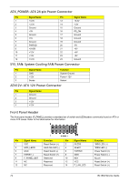
ATX_POWER: ATX 24-pin Power Connector, SYS_FAN: System Cooling FAN Power Connector, ATX12V: ATX 12V
 |
View all eMachines EL1852 manuals
Add to My Manuals
Save this manual to your list of manuals |
Page 80 highlights
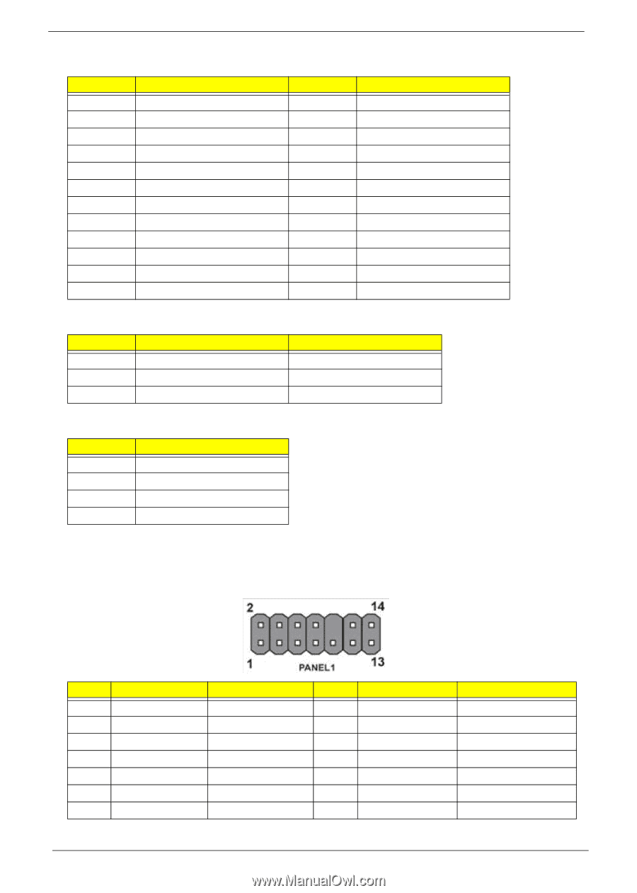
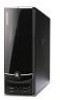
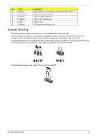
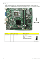
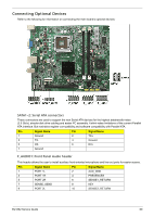
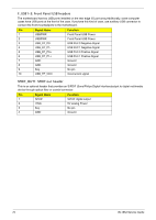
ATX_POWER: ATX 24-pin Power Connector Pin Signal Name 1 +3.3V 2 +3.3V 3 Ground 4 +5V 5 Ground 6 +5V 7 Ground 8 PWRGD 9 +5VSB 10 +12V 11 +12V 12 +3.3V Pin Signal Name 13 +3.3V 14 -12V 15 Ground 16 PS_ON 17 Ground 18 Ground 19 Ground 20 -5V 21 +5V 22 +5V 23 +5V 24 Ground SYS_FAN: System Cooling FAN Power Connector Pin Signal Name 1 GND 2 +12V 3 Sense Function System Ground Power +12V Sensor ATX12V: ATX 12V Power Connector Pin Signal Name 1 Ground 2 Ground 3 +12V 4 +12V Front Panel Header The front panel header (F_PANEL) provides a standard set of switch and LEDheaders commonly found on ATX or micro-ATX cases. Refer to the table below for information: Pin Signal Name Function Pin Signal Name 1 VCC Reset Switch (+) 2 GLED0 3 HDD_LEDN Hard disk LED (-) 4 GLED1 5 GND Reset Switch (-) 6 PWRSW 7 HWRST_L Reset Switch (+) 8 GND 9 F_PANEL_DET Reserved 10 KEY 11 NC Reserved 12 VCC 13 NC Reserved 14 F_LAN_LED Function *MSG LED (+) *MSG LED (-) Power Switch (+) Power Switch (-) No pin Reset Switch (+) Reset Switch (+) 72 EL1852 Service Guide
-
 1
1 -
2
-
3
-
4
-
5
-
6
-
7
-
8
-
9
-
10
-
11
-
12
-
13
-
14
-
15
-
16
-
17
-
18
-
19
-
20
-
21
-
22
-
23
-
24
-
25
-
26
-
27
-
28
-
29
-
30
-
31
-
32
-
33
-
34
-
35
-
36
-
37
-
38
-
39
-
40
-
41
-
42
-
43
-
44
-
45
-
46
-
47
-
48
-
49
-
50
-
51
-
52
-
53
-
54
-
55
-
56
-
57
-
58
-
59
-
60
-
61
-
62
-
63
-
64
-
65
-
66
-
67
-
68
-
69
-
70
-
71
-
72
-
73
-
74
-
 75
75 -
 76
76 -
 77
77 -
 78
78 -
 79
79 -
 80
80 -
 81
81 -
 82
82 -
 83
83 -
 84
84 -
 85
85 -
86
-
87
-
88
-
89
-
90
-
91
-
92
-
93
-
94
-
95
-
96
-
97
-
98
-
99
-
100
-
101
-
102
 |
 |