eMachines EL1852 eMachines EL1852 Service Guide - Page 51
Bootblock Recovery Code Checkpoints, POST Code Checkpoints, Disable NMI, Parity, video for EGA - manual
 |
View all eMachines EL1852 manuals
Add to My Manuals
Save this manual to your list of manuals |
Page 51 highlights
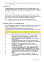
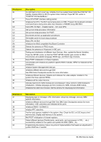
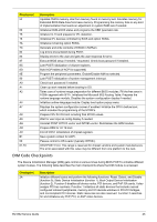
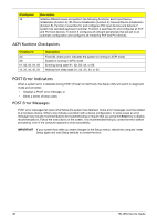
Checkpoint DA Description Restore CPUID value back into register. Give control to BIOS POST (ExecutePOSTKernel). See POST Code Checkpoints section of document for more information. Bootblock Recovery Code Checkpoints The Bootblock recovery code gets control when the BIOS determines that a BIOS recovery needs to occur because the user has forced the update or the BIOS checksum is corrupt. The following table describes the type of checkpoints that may occur during the Bootblock recovery portion of the BIOS. NOTE: Checkpoints may differ between different platforms based on system configuration. Checkpoints maychange due to vendor requirements, system chipset or option ROMs from add-in PCI devices. Checkpoint E0 E9 EA EB EF F0 F1 F2 F3 F5 FA FB F4 FC FD FF Description Initialize the floppy controller in the super I/O. Some interrupt vectors are initialized. DMA controller is initialized. 8259 interrupt controller is initialized. L1 cache is enabled. Set up floppy controller and data. Attempt to read from floppy. Enable ATAPI hardware. Attempt to read from ARMD and ATAPI CDROM. Disable ATAPI hardware. Jump back to checkpoint E9. Read error occurred on media. Jump back to checkpoint EB. Search for pre-defined recovery file name in root directory. Recovery file not found. Start reading FAT table and analyze FAT to find the clusters occupied by the recovery file. Start reading the recovery file cluster by cluster. Disable L1 cache. Check the validity of the recovery file configuration to the current configuration of the flash part. Make flash write enabled through chipset and OEM specific method. Detect proper flash part. Verify that the found flash part size equals the recovery file size. The recovery file size does not equal the found flash part size. Erase the flash part Program the flash part. The flash has been updated successfully. Make flash write disabled. Disable ATAPI hardware. Restore CPUID value back into register. Give control to F000 ROM at F000:FFF0h. POST Code Checkpoints The POST code checkpoints are the largest set of checkpoints during the BIOS preboot process. The following table describes the type of checkpoints that may occur during the POST portion of the BIOS. Checkpoint 03 04 05 Description Disable NMI, Parity, video for EGA, and DMA controllers. Initialize BIOS, POST, Runtime data area. Also initialize BIOS modules on POST entry and GPNV area. Initialized CMOS as mentioned in the Kernel Variable "wCMOSFlags." Check CMOS diagnostic byte to determine if battery power is OK and CMOS checksum is OK. Verify CMOS checksum manually by reading storage area. If the CMOS checksum is bad, update CMOS with power-on default values and clear passwords. Initialize status register A. Initializes data variables that are based on CMOS setup questions. Initializes both the 8259 compatible PICs in the system Initializes the interrupt controlling hardware (generally PIC) and interrupt vector table. EL1852 Service Guide 43
-
 1
1 -
2
-
3
-
4
-
5
-
6
-
7
-
8
-
9
-
10
-
11
-
12
-
13
-
14
-
15
-
16
-
17
-
18
-
19
-
20
-
21
-
22
-
23
-
24
-
25
-
26
-
27
-
28
-
29
-
30
-
31
-
32
-
33
-
34
-
35
-
36
-
37
-
38
-
39
-
40
-
41
-
42
-
43
-
44
-
45
-
 46
46 -
 47
47 -
 48
48 -
 49
49 -
 50
50 -
 51
51 -
 52
52 -
 53
53 -
 54
54 -
 55
55 -
 56
56 -
57
-
58
-
59
-
60
-
61
-
62
-
63
-
64
-
65
-
66
-
67
-
68
-
69
-
70
-
71
-
72
-
73
-
74
-
75
-
76
-
77
-
78
-
79
-
80
-
81
-
82
-
83
-
84
-
85
-
86
-
87
-
88
-
89
-
90
-
91
-
92
-
93
-
94
-
95
-
96
-
97
-
98
-
99
-
100
-
101
-
102
 |
 |