eMachines EL1852 eMachines EL1852 Service Guide - Page 49
Troubleshooting, Hardware Diagnostic Procedure
 |
View all eMachines EL1852 manuals
Add to My Manuals
Save this manual to your list of manuals |
Page 49 highlights
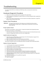
Troubleshooting Chapter 4 This chapter lists the POST error indicators and BIOS beep codes, as well general troubleshooting instructions. Hardware Diagnostic Procedure 1. Obtain as much detail as possible about the symptoms of the system failure. 2. Verify the symptoms by attempting to recreate the failure by running the diagnostic tests or repeating the same operation. 3. Refer to Power System Checkprocedure on the next section and the Beep Codessection on page 56 to determine which corrective action to take. System Check Procedures IMPORTANT The diagnostic tests described in this chapter are only intended to test Acer products. Non-Acer products, prototype cards, or modified options can give false errors and invalid system responses. Power System Check If the system can be powered on, skip this section. Proceed to the System Internal Inspectionprocedure. If the system will not power on, do the following: • Check if the power cable is properly connected to the AC power jack and a functional AC power source. • Check if the voltage selector switch is set to the correct voltage setting. System External Inspection 1. Inspect the power and LED indicators on the front panel. Go to Front Viewsection on page 4 for the location and description of the LED behaviour. 2. Make sure that the ventilation slots on the rear panel are not blocked. 3. Make sure that there is no point of contact in the system that can cause a power short. If the cause of the failure is still can not be determined, perform the System Internal Inspectionprocedure. System Internal Inspection 1. Turn off the power to the computer and all peripherals. 2. Unplug the power cord from the computer. 3. Unplug the network cable and all connected peripheral devices from the computer. 4. Place the computer on a flat, steady surface. 5. Remove the side panel as described in page 24. 6. Verify that the processor, memory module(s), and expansion board(s) are properly seated. 7. Verify that all power and data cables are firmly and properly attached to the installed drives. 8. Verify that all cable connections inside the system are firmly and properly attached to their appropriate mainboard connectors. 9. Verify that all components are Acer-qualified and supported. 10. Reinstall the side panel. 11. Power on the system. EL1852 Service Guide 41
-
 1
1 -
2
-
3
-
4
-
5
-
6
-
7
-
8
-
9
-
10
-
11
-
12
-
13
-
14
-
15
-
16
-
17
-
18
-
19
-
20
-
21
-
22
-
23
-
24
-
25
-
26
-
27
-
28
-
29
-
30
-
31
-
32
-
33
-
34
-
35
-
36
-
37
-
38
-
39
-
40
-
41
-
42
-
43
-
 44
44 -
 45
45 -
 46
46 -
 47
47 -
 48
48 -
 49
49 -
 50
50 -
 51
51 -
 52
52 -
 53
53 -
 54
54 -
55
-
56
-
57
-
58
-
59
-
60
-
61
-
62
-
63
-
64
-
65
-
66
-
67
-
68
-
69
-
70
-
71
-
72
-
73
-
74
-
75
-
76
-
77
-
78
-
79
-
80
-
81
-
82
-
83
-
84
-
85
-
86
-
87
-
88
-
89
-
90
-
91
-
92
-
93
-
94
-
95
-
96
-
97
-
98
-
99
-
100
-
101
-
102
 |
 |