3Com 5500-EI Getting Started Guide - Page 21
Switch 5500 - Rear View Detail, Switch 5500G-EI, - switch pwr
 |
UPC - 662705498997
View all 3Com 5500-EI manuals
Add to My Manuals
Save this manual to your list of manuals |
Page 21 highlights
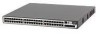
Switch 5500 - Rear View Detail 21 LED Color PWR LED Green Green flashing Yellow flashing Red Off Indicates The Switch is powered-up and operating normally. Self Test (POST) or Software Download is in progress. One or more ports have failed POST. The Switch has failed its Power On Self Test. The Switch is not receiving power or there is a fault with the Power Supply Unit. Switch 5500 - Rear View Detail Power Socket Figure 9 Switch 5500-SI, EI and FX - rear view Open Book Warning Labels NULL ~100-240V; 50/60Hz; 2.5A -48 -60V;2.0A Redundant Power System Socket Figure 10 Switch 5500-EI PWR - rear view Earthing Screw Power Socket NULL ~100-240V; 50/60Hz; 8.0A -53 -55V;19.5A Redundant Power System Socket Open Book Warning Labels Earthing Screw Switch 5500G-EI Power Socket Switch 5500G PoE PSU 24-Port NULL Figure 11 Switch 5500G-EI - rear view Stack LEDs Expansion Module Slot -52 - -55V;19.5A Redundant Power System Socket Handle UP DOWN Stacking: Green=OK, Flashing Green=Traffic, Yellow=Link Fault, Yellow Flashing=Stack Fault Stacking Cable Port (Up) Stacking Cable Port (Down)
-
 1
1 -
2
-
3
-
4
-
5
-
6
-
7
-
8
-
9
-
10
-
11
-
12
-
13
-
14
-
15
-
 16
16 -
 17
17 -
 18
18 -
 19
19 -
 20
20 -
 21
21 -
 22
22 -
 23
23 -
 24
24 -
 25
25 -
 26
26 -
27
-
28
-
29
-
30
-
31
-
32
-
33
-
34
-
35
-
36
-
37
-
38
-
39
-
40
-
41
-
42
-
43
-
44
-
45
-
46
-
47
-
48
-
49
-
50
-
51
-
52
-
53
-
54
-
55
-
56
-
57
-
58
-
59
-
60
-
61
-
62
-
63
-
64
-
65
-
66
-
67
-
68
-
69
-
70
-
71
-
72
-
73
-
74
-
75
-
76
-
77
-
78
-
79
-
80
-
81
-
82
-
83
-
84
-
85
-
86
-
87
-
88
-
89
-
90
-
91
-
92
-
93
-
94
-
95
-
96
-
97
-
98
-
99
-
100
-
101
-
102
-
103
-
104
-
105
-
106
-
107
-
108
-
109
-
110
-
111
-
112
-
113
-
114
-
115
-
116
-
117
-
118
-
119
-
120
-
121
-
122
-
123
-
124
-
125
-
126
-
127
-
128
-
129
-
130
-
131
-
132
-
133
-
134
-
135
-
136
-
137
-
138
-
139
-
140
-
141
-
142
-
143
-
144
-
145
-
146
-
147
-
148
-
149
-
150
-
151
 |
 |
