ATI 2400 User Guide - Page 12
Detailed Installation
 |
UPC - 727419413282
View all ATI 2400 manuals
Add to My Manuals
Save this manual to your list of manuals |
Page 12 highlights
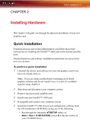
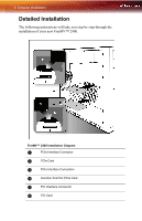
6 Detailed Installation Detailed Installation The following instructions will take you step by step through the installation of your new FireMV™ 2400. FireMV™ 2400 Installation Diagram X PCIe Interface Connector Y PCIe Card Z PCIe Interface Connection [ Insertion Point for PCIe Card \ PCI Interface Connector ] PCI Card
-
 1
1 -
2
-
3
-
4
-
5
-
6
-
 7
7 -
 8
8 -
 9
9 -
 10
10 -
 11
11 -
 12
12 -
 13
13 -
 14
14 -
 15
15 -
 16
16 -
 17
17 -
18
-
19
-
20
-
21
-
22
-
23
-
24
-
25
-
26
-
27
-
28
-
29
-
30
-
31
-
32
-
33
-
34
-
35
-
36
-
37
-
38
-
39
-
40
-
41
-
42
-
43
-
44
-
45
-
46
-
47
-
48
-
49
-
50
-
51
-
52
-
53
-
54
-
55
-
56
-
57
-
58
-
59
-
60
-
61
-
62
-
63
-
64
-
65
-
66
 |
 |

6
Detailed Installation
Detailed Installation
The following instructions will take you step by step through the
installation of your new FireMV™ 2400.
FireMV™ 2400 Installation Diagram
PCIe Interface Connector
PCIe Card
PCIe Interface Connection
Insertion Point for PCIe Card
PCI Interface Connector
PCI Card