ATI 2400 User Guide - Page 47
Minimizing Thermal Effects of Other Add-in Cards, Storage and Non-Operating Conditions
 |
UPC - 727419413282
View all ATI 2400 manuals
Add to My Manuals
Save this manual to your list of manuals |
Page 47 highlights
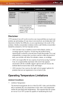
Operating Temperature Limitations 41 intake air at the top and at the inlet to the heat-sinks of the video card at 55°C or lower. Also, the back side of the card should not have a local ambient temperature of more than 45°C in the 5mm adjacent air layer. This must be ensured even when the inlet air to the chassis is at 35°C. Ideally the difference between the inlet temperature to the chassis and the inlet temperature to the thermal management device should be no more than 10°C. Furthermore, the system must deliver an approaching air velocity to each heat sink in the card of 75 to 100 Linear feet per minute (LFM). The air velocity is measured in distance of 0.1 inch away from the heat sink front row of fins. 2 Temperature Gradient The video card and its thermal management device should be able to operate at a temperature/time gradient of 15°C/h in its surrounding ambient. 3 Humidity The video card and its thermal management device should be able to operate in a RH (relative humidity) range of 10% to 80% without condensation. 4 Storage and Non-Operating Conditions The video card and its thermal management device should be stored or maintained in non-operating conditions in a RH range of 5% to 90% without condensation and an ambient temperature range of 40°C to 60°C. 5 Minimizing Thermal Effects of Other Add-in Cards To further ensure that the ambient temperature surrounding the graphics card is below 55°C, with a maximum input temperature of 35°C, the heat produced by other add-in cards in the system should be as far removed as possible. Hence it is recommended that any unused empty slots be between the graphics card and the add-in cards. In addition, the add-in cards should be placed in such order that the card closest to the graphics card is the one that produces the least amount of heat. An example would be a modem or network card first, followed by a sound card, then a tuner card or another Fire MV card.
-
 1
1 -
2
-
3
-
4
-
5
-
6
-
7
-
8
-
9
-
10
-
11
-
12
-
13
-
14
-
15
-
16
-
17
-
18
-
19
-
20
-
21
-
22
-
23
-
24
-
25
-
26
-
27
-
28
-
29
-
30
-
31
-
32
-
33
-
34
-
35
-
36
-
37
-
38
-
39
-
40
-
41
-
 42
42 -
 43
43 -
 44
44 -
 45
45 -
 46
46 -
 47
47 -
 48
48 -
 49
49 -
 50
50 -
 51
51 -
 52
52 -
53
-
54
-
55
-
56
-
57
-
58
-
59
-
60
-
61
-
62
-
63
-
64
-
65
-
66
 |
 |