Asus AW1500-I5 PP-DLW User Manual - Page 23
LPC super I/O controller.
 |
View all Asus AW1500-I5 manuals
Add to My Manuals
Save this manual to your list of manuals |
Page 23 highlights
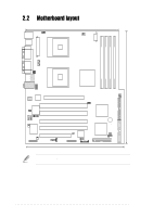
10 Intel® ICH4 I/O hub. The I/O Controller Hub 4 (ICH4) component contains the primary PCI interface, LPC interface, USB 2.0, ATA100, and other legacy functions. The ICH4 communicates with the MCH via the proprietary interconnect Hub Interface (HI1.5). 11 Flash ROM. This 4Mb firmware hub contains the programmable BIOS program. 12 PCI-X/PCI slots. One 64-bit/133MHz PCI-X slots, three 64-bit/ 100MHz PCI slot, and a 32-bit/33MHz PCI expansion slot support bus master PCI-X/PCI cards. 13 ASUS ASIC. This chip performs multiple system functions that include hardware and system voltage monitoring, IRQ routing, among others. 14 Standby power LED. This LED lights up if there is a standby power on the motherboard, and serves as a reminder to turn off the system power before plugging or unplugging devices. 15 LPC super I/O controller. This Low Pin Count (LPC) interface provides the commonly used Super I/O functionality. The chipset supports UART compatible serial ports, one parallel port with EPP and ECP capabilities, a floppy drive, and PS/2 keyboard and mouse. 16 Intel® 82540EM Gigabit LAN controller. This LAN controller is a single-chip solution for LAN on Motherboard (LOM) and Network Interface Card (NIC) applications. The chipset provides a 32-bit interface and supports 10/100/1000 Mbps data transfer rates. 17 PS/2 mouse port. This green 6-pin connector is for a PS/2 mouse. 18 Parallel port. This 25-pin port connects a parallel printer, a scanner, or other devices. 19 RJ-45 port. This port allows connection to a Local Area Network (LAN) through a network hub. 20 Line In port. This Line In (light blue) port connects a tape player or other audio sources. 21 Line Out port. This Line Out (lime) port connects a headphone or a speaker. 22 Microphone port. This Mic (pink) port connects a microphone. ASUS PP-DLW motherboard user guide 1-9
-
 1
1 -
2
-
3
-
4
-
5
-
6
-
7
-
8
-
9
-
10
-
11
-
12
-
13
-
14
-
15
-
16
-
17
-
 18
18 -
 19
19 -
 20
20 -
 21
21 -
 22
22 -
 23
23 -
 24
24 -
 25
25 -
 26
26 -
 27
27 -
 28
28 -
29
-
30
-
31
-
32
-
33
-
34
-
35
-
36
-
37
-
38
-
39
-
40
-
41
-
42
-
43
-
44
-
45
-
46
-
47
-
48
-
49
-
50
-
51
-
52
-
53
-
54
-
55
-
56
-
57
-
58
-
59
-
60
-
61
-
62
-
63
-
64
-
65
-
66
-
67
-
68
-
69
-
70
-
71
-
72
-
73
-
74
-
75
-
76
-
77
-
78
-
79
-
80
-
81
-
82
-
83
-
84
-
85
-
86
-
87
-
88
-
89
-
90
-
91
-
92
-
93
-
94
-
95
-
96
-
97
-
98
-
99
-
100
-
101
-
102
-
103
-
104
-
105
-
106
-
107
-
108
-
109
-
110
-
111
-
112
-
113
-
114
-
115
-
116
 |
 |