Asus AW1500-I5 PP-DLW User Manual - Page 48
Hardware information, CPU, Chassis, and Power Fan Connectors, pin FAN1, FAN2, FAN3, FAN4
 |
View all Asus AW1500-I5 manuals
Add to My Manuals
Save this manual to your list of manuals |
Page 48 highlights
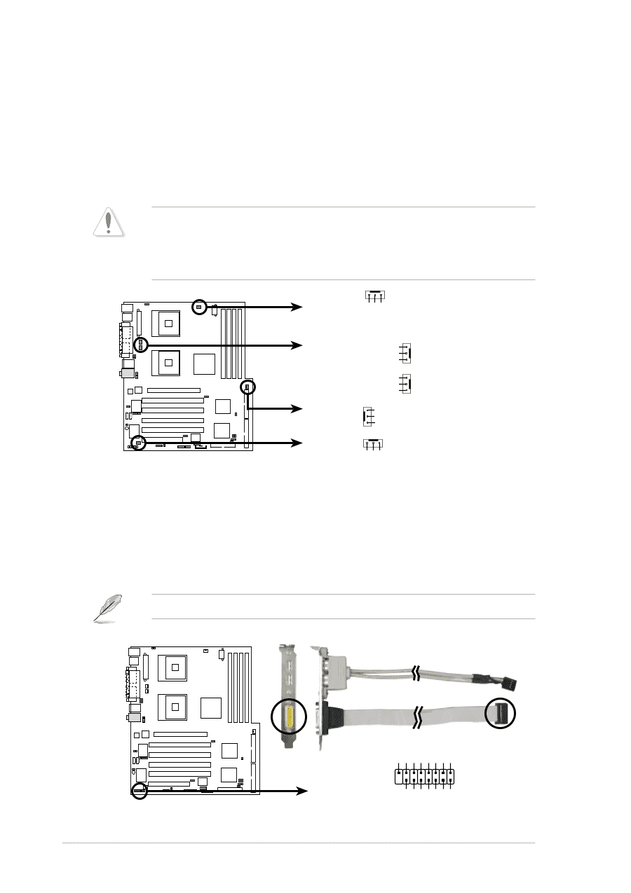
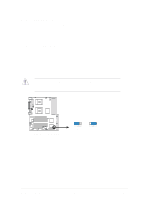
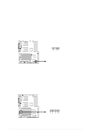
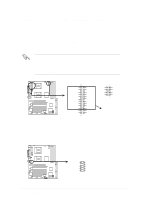
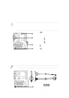
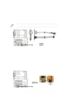
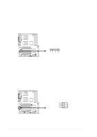
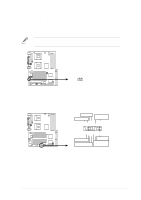
8. CPU, Chassis, and Power Fan Connectors (3-pin FAN1, FAN2, FAN3, FAN4, FAN5) The fan connectors support cooling fans of 350mA~740mA (8.88W max.) or a total of 1A~2.22A (26.64W max.) at +12V. Connect the fan cables to the fan connectors on the motherboard, making sure that the black wire of each cable matches the ground pin of the connector. Do not forget to connect the fan cables to the fan connectors. Lack of sufficient air flow within the system may damage the motherboard components. These are not jumpers! DO NOT place jumper caps on the fan connectors! FAN1 Rotation +12V GND FAN3 FAN2 Rotation +12V GND Rotation +12V GND FAN4 GND +12V Rotation FAN5 PP-DLW PP-DLW 12-Volt Cooling Fan Power Rotation +12V GND 9. GAME/MIDI connector (16-1 pin GAME1) This connector supports a GAME/MIDI module. The GAME/MIDI port on the module connects a joystick or a game pad for playing games, and MIDI devices for playing or editing audio files. The GAME/MIDI module is separately purchased. +5V J1B2 J1CY GND GND J1CX J1B1 +5V PP-DLW PP-DLW Game Connector 2-22 8 1 GAME1 16 9 MIDI_IN J2B2 J2CY MIDI_OUT J2CX J2B1 +5V Chapter 2: Hardware information
-
 1
1 -
2
-
3
-
4
-
5
-
6
-
7
-
8
-
9
-
10
-
11
-
12
-
13
-
14
-
15
-
16
-
17
-
18
-
19
-
20
-
21
-
22
-
23
-
24
-
25
-
26
-
27
-
28
-
29
-
30
-
31
-
32
-
33
-
34
-
35
-
36
-
37
-
38
-
39
-
40
-
41
-
42
-
 43
43 -
 44
44 -
 45
45 -
 46
46 -
 47
47 -
 48
48 -
 49
49 -
 50
50 -
 51
51 -
 52
52 -
 53
53 -
54
-
55
-
56
-
57
-
58
-
59
-
60
-
61
-
62
-
63
-
64
-
65
-
66
-
67
-
68
-
69
-
70
-
71
-
72
-
73
-
74
-
75
-
76
-
77
-
78
-
79
-
80
-
81
-
82
-
83
-
84
-
85
-
86
-
87
-
88
-
89
-
90
-
91
-
92
-
93
-
94
-
95
-
96
-
97
-
98
-
99
-
100
-
101
-
102
-
103
-
104
-
105
-
106
-
107
-
108
-
109
-
110
-
111
-
112
-
113
-
114
-
115
-
116
 |
 |