Asus Crosshair II Formula User Manual - Page 28
Memory LED, Southbridge / Bridge PCIe LEDs
 |
UPC - 610839160044
View all Asus Crosshair II Formula manuals
Add to My Manuals
Save this manual to your list of manuals |
Page 28 highlights
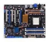
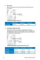
2. Memory LED Refer to the illustration below for the LED location and the table below for LED definition. CROSSHAIR II FORMULA ® DDR_CRAZY DDR_HIGH DDR_NORMAL RESET CROSSHAIR II FORMULA DDR LED DDR2 Voltage Normal (green) 1.80-2.10 High (yellow) 2.12-2.50 Crazy (red) 2.52- 3. Southbridge / Bridge (PCIe) LEDs The Southbridge LED has two different voltage displays: SB Voltage or HT Voltage; you can select the voltage to display in BIOS. The Bridge (PCIe) LED displays BR Voltage. Refer to the illustration below for the LED location and the table below for LED definition. CROSSHAIR II FORMULA ® SB_CRAZY SB_HIGH SB_NORMAL BR_CRAZY BR_HIGH BR_NORMAL RESET CROSSHAIR II FORMULA Southbridge/Bridge(PCIe) LED SB Voltage HT Voltage BR Voltage Normal (green) 1.10-1.30 1.20-1.40 1.20-1.40 High (yellow) 1.32-1.50 1.42-1.60 1.42-1.60 Crazy (red) 1.52- 1.62- 1.62- 2-2 Chapter 2: Hardware information
-
 1
1 -
2
-
3
-
4
-
5
-
6
-
7
-
8
-
9
-
10
-
11
-
12
-
13
-
14
-
15
-
16
-
17
-
18
-
19
-
20
-
21
-
22
-
 23
23 -
 24
24 -
 25
25 -
 26
26 -
 27
27 -
 28
28 -
 29
29 -
 30
30 -
 31
31 -
 32
32 -
 33
33 -
34
-
35
-
36
-
37
-
38
-
39
-
40
-
41
-
42
-
43
-
44
-
45
-
46
-
47
-
48
-
49
-
50
-
51
-
52
-
53
-
54
-
55
-
56
-
57
-
58
-
59
-
60
-
61
-
62
-
63
-
64
-
65
-
66
-
67
-
68
-
69
-
70
-
71
-
72
-
73
-
74
-
75
-
76
-
77
-
78
-
79
-
80
-
81
-
82
-
83
-
84
-
85
-
86
-
87
-
88
-
89
-
90
-
91
-
92
-
93
-
94
-
95
-
96
-
97
-
98
-
99
-
100
-
101
-
102
-
103
-
104
-
105
-
106
-
107
-
108
-
109
-
110
-
111
-
112
-
113
-
114
-
115
-
116
-
117
-
118
-
119
-
120
-
121
-
122
-
123
-
124
-
125
-
126
-
127
-
128
-
129
-
130
-
131
-
132
-
133
-
134
-
135
-
136
-
137
-
138
-
139
-
140
-
141
-
142
-
143
-
144
-
145
-
146
-
147
-
148
-
149
-
150
-
151
-
152
-
153
-
154
-
155
-
156
-
157
-
158
-
159
-
160
-
161
-
162
-
163
-
164
-
165
-
166
-
167
-
168
-
169
-
170
-
171
-
172
-
173
-
174
-
175
-
176
-
177
-
178
-
179
-
180
-
181
-
182
-
183
-
184
-
185
-
186
 |
 |
