Asus Crosshair II Formula User Manual - Page 91
VDDNB Voltage [Auto], DDR2 Voltage [Auto], SB Voltage [Auto], HT Voltage [Auto], VDDA Voltage [Auto
 |
UPC - 610839160044
View all Asus Crosshair II Formula manuals
Add to My Manuals
Save this manual to your list of manuals |
Page 91 highlights
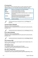
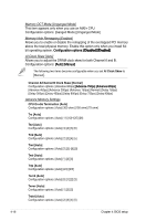
Refer to the CPU documentation before setting the CPU voltage. Setting a high voltage may damage the CPU permanently, and setting a low voltage may make the system unstable. VDDNB Voltage [Auto] Allows you to select the VDDNB voltage. Configuration options: [Auto] [+100mvV] [+150mvV] [+200mvV] [+250mvV] [+300mvV] [+350mvV] [+450mvV] DDR2 Voltage [Auto] Allows you to select the Memory voltage. The text color in the configuration field corresponds to the onboard Memory LED color, both of which indicate voltage condition. Refer to page 2-2 for Memory LED definition. Configuration options: [Auto] [1.800V] [1.820V] [1.840V]-[3.380V] [3.400V] SB Voltage [Auto] Allows you to select the Southbridge voltage. The text color in the configuration field corresponds to the onboard Southbridge LED color, both of which indicate voltage condition. When you set the SB LED Selection item to [SB Voltage], the onboard Southbridge LED displays Southbridge voltage condition. Refer to page 2-2 for Southbridge LED definition. Configuration options: [Auto] [1.10V] [1.12V] [1.14V] [1.16V]-[2.98V] [3.00V] HT Voltage [Auto] Allows you to select the HT voltage. The text color in the configuration field corresponds to the onboard Southbridge LED color, both of which indicate voltage condition. When you set the SB LED Selection item to [HT Voltage], the onboard Southbridge LED displays HT voltage condition. Refer to page 2-2 for Southbridge LED definition. Configuration options: [Auto] [1.20V] [1.22V] [1.24V] [1.26V]-[2.98V] [3.00V] VDDA Voltage [Auto] Allows you to select the VDDA voltage. Configuration options: [Auto] [2.50V] [2.62V] [2.72V] [2.82V]-[2.92V] [3.02V] BR Voltage [Auto] Allows you to select the Bridge (PCIe) voltage. The text color in the configuration field corresponds to the onboard Bridge (PCIe) LED color, both of which indicate voltage condition. Refer to page 2-2 for Bridge (PCIe) LED definition. Configuration options: [Auto] [1.20V] [1.22V] [1.24V] [1.26V]-[2.98V] [3.00V] ASUS Crosshair II Formula 4-19
-
 1
1 -
2
-
3
-
4
-
5
-
6
-
7
-
8
-
9
-
10
-
11
-
12
-
13
-
14
-
15
-
16
-
17
-
18
-
19
-
20
-
21
-
22
-
23
-
24
-
25
-
26
-
27
-
28
-
29
-
30
-
31
-
32
-
33
-
34
-
35
-
36
-
37
-
38
-
39
-
40
-
41
-
42
-
43
-
44
-
45
-
46
-
47
-
48
-
49
-
50
-
51
-
52
-
53
-
54
-
55
-
56
-
57
-
58
-
59
-
60
-
61
-
62
-
63
-
64
-
65
-
66
-
67
-
68
-
69
-
70
-
71
-
72
-
73
-
74
-
75
-
76
-
77
-
78
-
79
-
80
-
81
-
82
-
83
-
84
-
85
-
 86
86 -
 87
87 -
 88
88 -
 89
89 -
 90
90 -
 91
91 -
 92
92 -
 93
93 -
 94
94 -
 95
95 -
 96
96 -
97
-
98
-
99
-
100
-
101
-
102
-
103
-
104
-
105
-
106
-
107
-
108
-
109
-
110
-
111
-
112
-
113
-
114
-
115
-
116
-
117
-
118
-
119
-
120
-
121
-
122
-
123
-
124
-
125
-
126
-
127
-
128
-
129
-
130
-
131
-
132
-
133
-
134
-
135
-
136
-
137
-
138
-
139
-
140
-
141
-
142
-
143
-
144
-
145
-
146
-
147
-
148
-
149
-
150
-
151
-
152
-
153
-
154
-
155
-
156
-
157
-
158
-
159
-
160
-
161
-
162
-
163
-
164
-
165
-
166
-
167
-
168
-
169
-
170
-
171
-
172
-
173
-
174
-
175
-
176
-
177
-
178
-
179
-
180
-
181
-
182
-
183
-
184
-
185
-
186
 |
 |
