Asus P4P800-E DELUXE P4P800-E Deluxe User's manual for English Version E1867 - Page 52
Hardware information, CPU, Chassis, and Power Fan Connectors, pin CPU_FAN, PWR_FAN,
 |
View all Asus P4P800-E DELUXE manuals
Add to My Manuals
Save this manual to your list of manuals |
Page 52 highlights
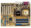
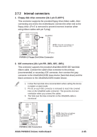
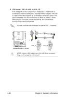
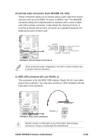
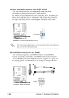
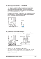
6. CPU, Chassis and Power Fan Connectors (3-pin CPU_FAN, PWR_FAN, CHA_FAN) The fan connectors support cooling fans of 350mA~740mA (8.88W max.) or a total of 1A~2.22A (26.64W max.) at +12V. Connect the fan cables to the fan connectors on the motherboard, making sure that the black wire of each cable matches the ground pin of the connector. Do not forget to connect the fan cables to the fan connectors. Lack of sufficient air flow within the system may damage the motherboard components. These are not jumpers! DO NOT place jumper caps on the fan connectors! GND +12V Rotation CPU_FAN GND +12V Rotation ® CHA_FAN GND +12V Rotation P4P800-E PWR_FAN P4P800-E 12-Volt Fan Connectors 7. Serial Port 2 connector (10-1 pin COM2) This connector accomodates a second serial port using a serial port bracket. Connect the bracket cable to this connector then install the bracket into a slot opening at the back of the system chassis. COM2 PIN 1 ® P4P800-E P4P800-E Serial COM2 Bracket The serial port bracket is purchased separately. 2-30 Chapter 2: Hardware information
-
 1
1 -
2
-
3
-
4
-
5
-
6
-
7
-
8
-
9
-
10
-
11
-
12
-
13
-
14
-
15
-
16
-
17
-
18
-
19
-
20
-
21
-
22
-
23
-
24
-
25
-
26
-
27
-
28
-
29
-
30
-
31
-
32
-
33
-
34
-
35
-
36
-
37
-
38
-
39
-
40
-
41
-
42
-
43
-
44
-
45
-
46
-
 47
47 -
 48
48 -
 49
49 -
 50
50 -
 51
51 -
 52
52 -
 53
53 -
 54
54 -
 55
55 -
 56
56 -
 57
57 -
58
-
59
-
60
-
61
-
62
-
63
-
64
-
65
-
66
-
67
-
68
-
69
-
70
-
71
-
72
-
73
-
74
-
75
-
76
-
77
-
78
-
79
-
80
-
81
-
82
-
83
-
84
-
85
-
86
-
87
-
88
-
89
-
90
-
91
-
92
-
93
-
94
-
95
-
96
-
97
-
98
-
99
-
100
-
101
-
102
-
103
-
104
-
105
-
106
-
107
-
108
-
109
-
110
-
111
-
112
-
113
-
114
-
115
-
116
-
117
-
118
-
119
-
120
-
121
-
122
-
123
-
124
-
125
-
126
-
127
-
128
-
129
-
130
-
131
-
132
-
133
-
134
-
135
-
136
-
137
-
138
-
139
-
140
-
141
-
142
-
143
 |
 |