Asus P4P800-E DELUXE P4P800-E Deluxe User's manual for English Version E1867 - Page 58
ATX Power Switch / Soft-Off Switch Lead Yellow 2-pin PWRBTN - reset bios
 |
View all Asus P4P800-E DELUXE manuals
Add to My Manuals
Save this manual to your list of manuals |
Page 58 highlights
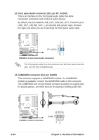
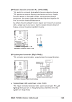
• System Warning Speaker Lead (Orange 4-pin SPKR) This 4-pin connector connects to the case-mounted speaker and allows you to hear system beeps and warnings. • Reset Switch Lead (Blue 2-pin RESET) This 2-pin connector connects to the case-mounted reset switch for rebooting the system without turning off the system power. • ATX Power Switch / Soft-Off Switch Lead (Yellow 2-pin PWRBTN ) This connector connects a switch that controls the system power. Pressing the power switch turns the system between ON and SLEEP, or ON and SOFT OFF, depending on the BIOS or OS settings. Pressing the power switch while in the ON mode for more than 4 seconds turns the system OFF. • System Management Interrupt Lead (Light Blue 2-pin SMI) This 2-pin connector allows you to manually place the system into a suspended mode, or "green" mode, where system activity is instantly decreased to save power and to expand the life of certain system components. Attach the case-mounted suspend switch to this 2-pin connector. • Hard disk activity LED (Red 2-pin IDE_LED) This connector supplies power to the hard disk activity LED. Any read or write activity of an IDE device cause this LED to light up. The System Panel connector is color-coded for easy and foolproof connection. Take note of the specific connector colors as described. 2-36 Chapter 2: Hardware information
-
 1
1 -
2
-
3
-
4
-
5
-
6
-
7
-
8
-
9
-
10
-
11
-
12
-
13
-
14
-
15
-
16
-
17
-
18
-
19
-
20
-
21
-
22
-
23
-
24
-
25
-
26
-
27
-
28
-
29
-
30
-
31
-
32
-
33
-
34
-
35
-
36
-
37
-
38
-
39
-
40
-
41
-
42
-
43
-
44
-
45
-
46
-
47
-
48
-
49
-
50
-
51
-
52
-
 53
53 -
 54
54 -
 55
55 -
 56
56 -
 57
57 -
 58
58 -
 59
59 -
 60
60 -
 61
61 -
 62
62 -
 63
63 -
64
-
65
-
66
-
67
-
68
-
69
-
70
-
71
-
72
-
73
-
74
-
75
-
76
-
77
-
78
-
79
-
80
-
81
-
82
-
83
-
84
-
85
-
86
-
87
-
88
-
89
-
90
-
91
-
92
-
93
-
94
-
95
-
96
-
97
-
98
-
99
-
100
-
101
-
102
-
103
-
104
-
105
-
106
-
107
-
108
-
109
-
110
-
111
-
112
-
113
-
114
-
115
-
116
-
117
-
118
-
119
-
120
-
121
-
122
-
123
-
124
-
125
-
126
-
127
-
128
-
129
-
130
-
131
-
132
-
133
-
134
-
135
-
136
-
137
-
138
-
139
-
140
-
141
-
142
-
143
 |
 |