Asus SP97-XV User Manual - Page 26
Floppy Disk Drive Connector 34-1pin FLOPPY
 |
View all Asus SP97-XV manuals
Add to My Manuals
Save this manual to your list of manuals |
Page 26 highlights
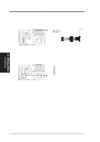
R R III. INSTALLATION (Connectors) III. INSTALLATION 6. IrDA / Fast IR-Compliant infrared module connector (6-pin IR) This connector supports the optional wireless transmitting and receiving infrared module. This module mounts to a small opening on system cases that support this feature. Front View Back View (NC) GND +5V IRRX IRTX Infrared Module Connector IRTX +5V GND (NC) IRRX For the infrared feature to be available, you must connect an optional Infrared module to the motherboard. 7. Floppy Disk Drive Connector (34-1pin FLOPPY) This connector supports the provided floppy drive ribbon cable. After connecting the single end to the board, connect the two plugs on the other end to the floppy drives. (Pin 5 is removed to prevent inserting in the wrong orientation when using ribbon cables with pin 5 plugged). Floppy Disk Drive Connector NOTE: Orient the red stripe to Pin 1 Pin 1 26 ASUS SP97-XV User's Manual
-
 1
1 -
2
-
3
-
4
-
5
-
6
-
7
-
8
-
9
-
10
-
11
-
12
-
13
-
14
-
15
-
16
-
17
-
18
-
19
-
20
-
 21
21 -
 22
22 -
 23
23 -
 24
24 -
 25
25 -
 26
26 -
 27
27 -
 28
28 -
 29
29 -
 30
30 -
 31
31 -
32
-
33
-
34
-
35
-
36
-
37
-
38
-
39
-
40
-
41
-
42
-
43
-
44
-
45
-
46
-
47
-
48
-
49
-
50
-
51
-
52
-
53
-
54
-
55
-
56
-
57
-
58
-
59
-
60
-
61
-
62
-
63
-
64
-
65
-
66
-
67
-
68
-
69
-
70
-
71
-
72
-
73
-
74
-
75
-
76
-
77
-
78
-
79
-
80
-
81
-
82
-
83
-
84
-
85
-
86
-
87
-
88
-
89
-
90
 |
 |
