Asus SP97-XV User Manual - Page 27
IDE activity LED 4-1pin IDE_LED
 |
View all Asus SP97-XV manuals
Add to My Manuals
Save this manual to your list of manuals |
Page 27 highlights
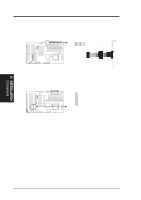
III. INSTALLATION 8. Primary / Secondary IDE connectors (Two 40-1pin IDE) These connectors support the provided IDE hard disk ribbon cable. After connecting the single end to the board, connect the two plugs at the other end to your hard disk(s). If you install two hard disks, you must configure the second drive to Slave mode by setting its jumper accordingly. Please refer to the documentation of your hard disk for the jumper settings. (Pin 20 is removed to prevent inserting in the wrong orientation when using ribbon cables with pin 20 plugged). NOTE: Orient the red stripe to Pin 1 Pin 1 Secondary IDE Connector Primary IDE Connector IDE Connectors 9. IDE activity LED (4-1pin IDE_LED) This connector supplies power to the cabinet's IDE activity LED. Read and write activity by devices connected to the Primary or Secondary IDE connectors will cause the LED to light up. R R IDE Activity LED TIP: If the case-mounted LED does not light, try reversing the 2-pin plug. IDE Signal +5V III. INSTALLATION (Connectors) ASUS SP97-XV User's Manual 27
-
 1
1 -
2
-
3
-
4
-
5
-
6
-
7
-
8
-
9
-
10
-
11
-
12
-
13
-
14
-
15
-
16
-
17
-
18
-
19
-
20
-
21
-
 22
22 -
 23
23 -
 24
24 -
 25
25 -
 26
26 -
 27
27 -
 28
28 -
 29
29 -
 30
30 -
 31
31 -
 32
32 -
33
-
34
-
35
-
36
-
37
-
38
-
39
-
40
-
41
-
42
-
43
-
44
-
45
-
46
-
47
-
48
-
49
-
50
-
51
-
52
-
53
-
54
-
55
-
56
-
57
-
58
-
59
-
60
-
61
-
62
-
63
-
64
-
65
-
66
-
67
-
68
-
69
-
70
-
71
-
72
-
73
-
74
-
75
-
76
-
77
-
78
-
79
-
80
-
81
-
82
-
83
-
84
-
85
-
86
-
87
-
88
-
89
-
90
 |
 |
