Asus Terminator C3 Terminator C3V User Manual - Page 14
Rear panel - audio
 |
View all Asus Terminator C3 manuals
Add to My Manuals
Save this manual to your list of manuals |
Page 14 highlights
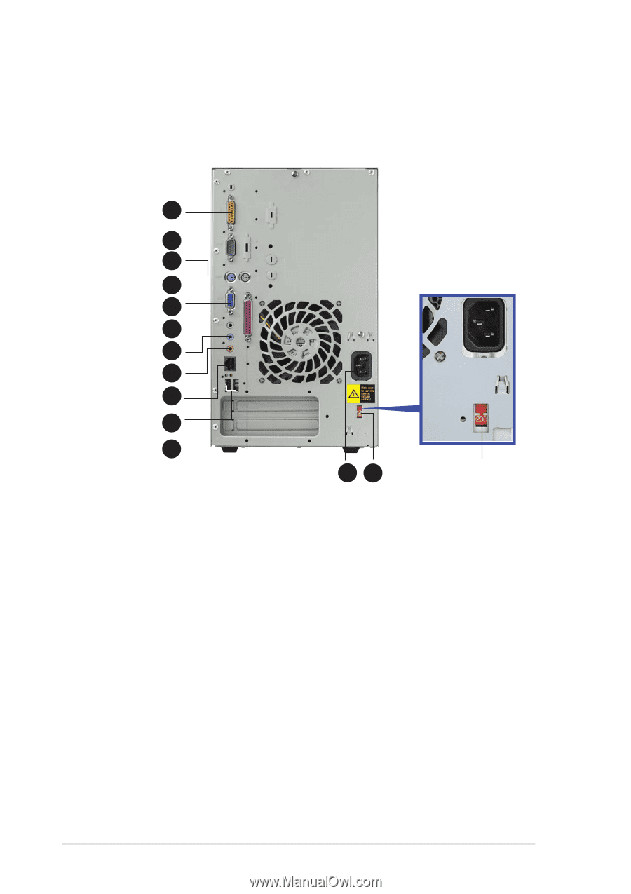
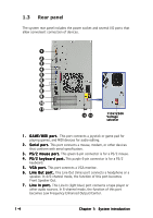
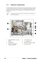
1.3 Rear panel The system rear panel includes the power socket and several I/O ports that allow convenient connection of devices. 1 2 3 4 5 6 7 8 9 10 11 12 13 115V/230V Voltage selector 1 . G A M E / M I D I p o r t . This port connects a joystick or game pad for playing games, and MIDI devices for audio editing. 2 . S e r i a l p o r t . This port connects a mouse, modem, or other devices that conform with serial specification. 3 . P S / 2 m o u s e p o r t . This green 6-pin connector is for a PS/2 mouse. 4 . P S / 2 k e y b o a r d p o r t . This purple 6-pin connector is for a PS/2 keyboard. 5 . V G A p o r t . This port connects a VGA monitor. 6 . L i n e O u t p o r t . This Line Out (lime) port connects a headphone or a speaker. In 4/6-channel mode, the function of this port becomes Front Speaker Out. 7 . L i n e I n p o r t . This Line In (light blue) port connects a tape player or other audio sources. In 6-channel mode, the function of this port becomes Low Frequency Enhanced Output/Center. 1-4 Chapter 1: System introduction
-
 1
1 -
2
-
3
-
4
-
5
-
6
-
7
-
8
-
 9
9 -
 10
10 -
 11
11 -
 12
12 -
 13
13 -
 14
14 -
 15
15 -
 16
16 -
 17
17 -
 18
18 -
 19
19 -
20
-
21
-
22
-
23
-
24
-
25
-
26
-
27
-
28
-
29
-
30
-
31
-
32
-
33
-
34
-
35
-
36
-
37
-
38
-
39
-
40
-
41
-
42
-
43
-
44
-
45
-
46
-
47
-
48
-
49
-
50
-
51
-
52
-
53
-
54
-
55
-
56
-
57
-
58
-
59
-
60
-
61
-
62
-
63
-
64
-
65
-
66
-
67
-
68
-
69
-
70
-
71
-
72
-
73
-
74
-
75
-
76
-
77
-
78
-
79
-
80
-
81
-
82
-
83
-
84
-
85
-
86
-
87
-
88
-
89
-
90
-
91
-
92
-
93
-
94
 |
 |