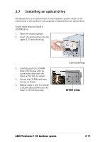
Asus Terminator C3 Terminator C3V User Manual - Page 28
the CD-ROM.
 |
View all Asus Terminator C3 manuals
Add to My Manuals
Save this manual to your list of manuals |
Page 28 highlights
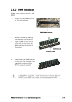
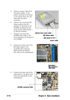
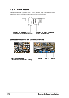
5. Connect a power cable from the power supply to the power connector at the back of the optical drive. Use the cable with the white connector. 6. Connect one end of the IDE ribbon cable to the IDE interface at the back of the CD-ROM, matching the red stripe on the cable with Pin 1 on the IDE interface. 7. Connect one end of the Optical drive audio cable CD-ROM audio cable to the IDE ribbon cable 4-pin connector at the back of the CD-ROM. Red stripe to Pin 1 Power cable 8. Connect the other end of the IDE ribbon cable to the secondary IDE connector (black connector labeled SEC_IDE) on the motherboard. 9. Connect the other end of the audio cable to the black 4-pin connector labeled CD on the motherboard. Secondary IDE connector (SEC_IDE) CD-ROM connector (CD) 2-12 Chapter 2: Basic Installation
-
 1
1 -
2
-
3
-
4
-
5
-
6
-
7
-
8
-
9
-
10
-
11
-
12
-
13
-
14
-
15
-
16
-
17
-
18
-
19
-
20
-
21
-
22
-
 23
23 -
 24
24 -
 25
25 -
 26
26 -
 27
27 -
 28
28 -
 29
29 -
 30
30 -
 31
31 -
 32
32 -
 33
33 -
34
-
35
-
36
-
37
-
38
-
39
-
40
-
41
-
42
-
43
-
44
-
45
-
46
-
47
-
48
-
49
-
50
-
51
-
52
-
53
-
54
-
55
-
56
-
57
-
58
-
59
-
60
-
61
-
62
-
63
-
64
-
65
-
66
-
67
-
68
-
69
-
70
-
71
-
72
-
73
-
74
-
75
-
76
-
77
-
78
-
79
-
80
-
81
-
82
-
83
-
84
-
85
-
86
-
87
-
88
-
89
-
90
-
91
-
92
-
93
-
94
 |
 |
