Asus Terminator C3 Terminator C3V User Manual - Page 20
Detaching the drive frame
 |
View all Asus Terminator C3 manuals
Add to My Manuals
Save this manual to your list of manuals |
Page 20 highlights
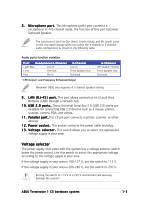
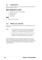
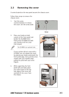
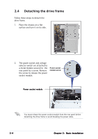
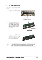
2.4 Detaching the drive frame Follow these steps to detach the drive frame. 1. Place the chassis on a flat surface and turn it on its side. 2. The power socket and voltage selector switch are attached to a metal module secured to the Power socket rear panel by a screw. Remove module screw the screw to release the power socket module. Power socket module You must release the power socket module from the rear panel before detaching the drive frame to avoid breaking the power cable. 2-4 Chapter 2: Basic Installation
-
 1
1 -
2
-
3
-
4
-
5
-
6
-
7
-
8
-
9
-
10
-
11
-
12
-
13
-
14
-
 15
15 -
 16
16 -
 17
17 -
 18
18 -
 19
19 -
 20
20 -
 21
21 -
 22
22 -
 23
23 -
 24
24 -
 25
25 -
26
-
27
-
28
-
29
-
30
-
31
-
32
-
33
-
34
-
35
-
36
-
37
-
38
-
39
-
40
-
41
-
42
-
43
-
44
-
45
-
46
-
47
-
48
-
49
-
50
-
51
-
52
-
53
-
54
-
55
-
56
-
57
-
58
-
59
-
60
-
61
-
62
-
63
-
64
-
65
-
66
-
67
-
68
-
69
-
70
-
71
-
72
-
73
-
74
-
75
-
76
-
77
-
78
-
79
-
80
-
81
-
82
-
83
-
84
-
85
-
86
-
87
-
88
-
89
-
90
-
91
-
92
-
93
-
94
 |
 |
2-4
2-4
2-4
2-4
2-4
Chapter 2:
Basic Installation
Chapter 2:
Basic Installation
Chapter 2:
Basic Installation
Chapter 2:
Basic Installation
Chapter 2:
Basic Installation
2.4
Detaching the drive frame
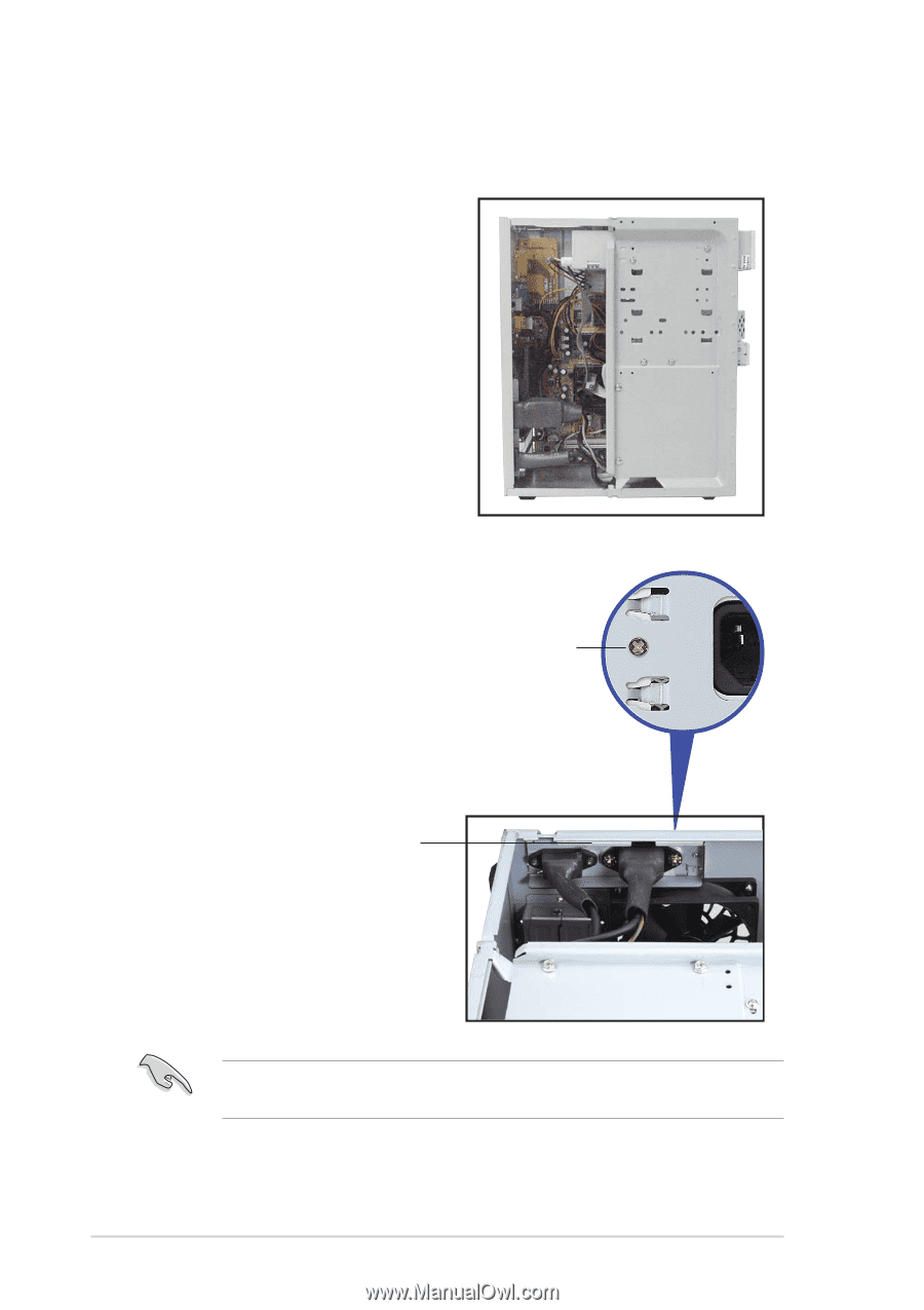
You must release the power socket module from the rear panel before
detaching the drive frame to avoid breaking the power cable.
Follow these steps to detach the
drive frame.
1.
Place the chassis on a flat
surface and turn it on its side.
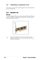
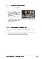
2.
The power socket and voltage
selector switch are attached to
a metal module secured to
the
rear panel by a screw. Remove
the screw to release the power
socket module.
Power socket
module screw
Power socket module
Power socket module
Power socket module
Power socket module
Power socket module