Asus Terminator C3 Terminator C3V User Manual - Page 35
Connecting external devices
 |
View all Asus Terminator C3 manuals
Add to My Manuals
Save this manual to your list of manuals |
Page 35 highlights
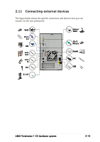
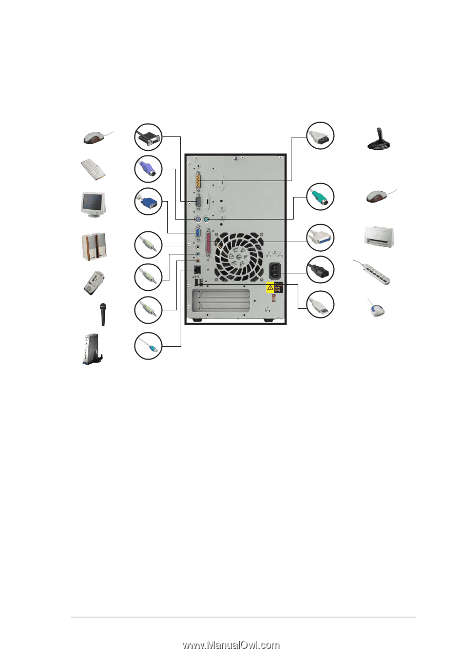
2.11 Connecting external devices The figure below shows the specific connectors and devices that you can connect to the rear panel ports. Serial PS/2 KB VGA Line Out Line In Mic RJ-45 Game/ MIDI PS/2 Mouse Parallel AC USB ASUS Terminator 1 C3 barebone system 2-19
-
 1
1 -
2
-
3
-
4
-
5
-
6
-
7
-
8
-
9
-
10
-
11
-
12
-
13
-
14
-
15
-
16
-
17
-
18
-
19
-
20
-
21
-
22
-
23
-
24
-
25
-
26
-
27
-
28
-
29
-
 30
30 -
 31
31 -
 32
32 -
 33
33 -
 34
34 -
 35
35 -
 36
36 -
 37
37 -
 38
38 -
 39
39 -
 40
40 -
41
-
42
-
43
-
44
-
45
-
46
-
47
-
48
-
49
-
50
-
51
-
52
-
53
-
54
-
55
-
56
-
57
-
58
-
59
-
60
-
61
-
62
-
63
-
64
-
65
-
66
-
67
-
68
-
69
-
70
-
71
-
72
-
73
-
74
-
75
-
76
-
77
-
78
-
79
-
80
-
81
-
82
-
83
-
84
-
85
-
86
-
87
-
88
-
89
-
90
-
91
-
92
-
93
-
94
 |
 |
ASUS Terminator 1 C3 barebone system
ASUS Terminator 1 C3 barebone system
ASUS Terminator 1 C3 barebone system
ASUS Terminator 1 C3 barebone system
ASUS Terminator 1 C3 barebone system
2-19
2-19
2-19
2-19
2-19
2.11
Connecting external devices
The figure below shows the specific connectors and devices that you can
connect to the rear panel ports.
Serial
Serial
Serial
Serial
Serial
PS/2
PS/2
PS/2
PS/2
PS/2
KB
KB
KB
KB
KB
VGA
VGA
VGA
VGA
VGA
Line
Line
Line
Line
Line
Out
Out
Out
Out
Out
Line
Line
Line
Line
Line
In
In
In
In
In
Mic
Mic
Mic
Mic
Mic
Game/
Game/
Game/
Game/
Game/
MIDI
MIDI
MIDI
MIDI
MIDI
PS/2
PS/2
PS/2
PS/2
PS/2
Mouse
Mouse
Mouse
Mouse
Mouse
AC
AC
AC
AC
AC
Parallel
Parallel
Parallel
Parallel
Parallel
USB
USB
USB
USB
USB
RJ-45
RJ-45
RJ-45
RJ-45
RJ-45