Asus Terminator C3 Terminator C3V User Manual - Page 77
Chipset Configuration
 |
View all Asus Terminator C3 manuals
Add to My Manuals
Save this manual to your list of manuals |
Page 77 highlights
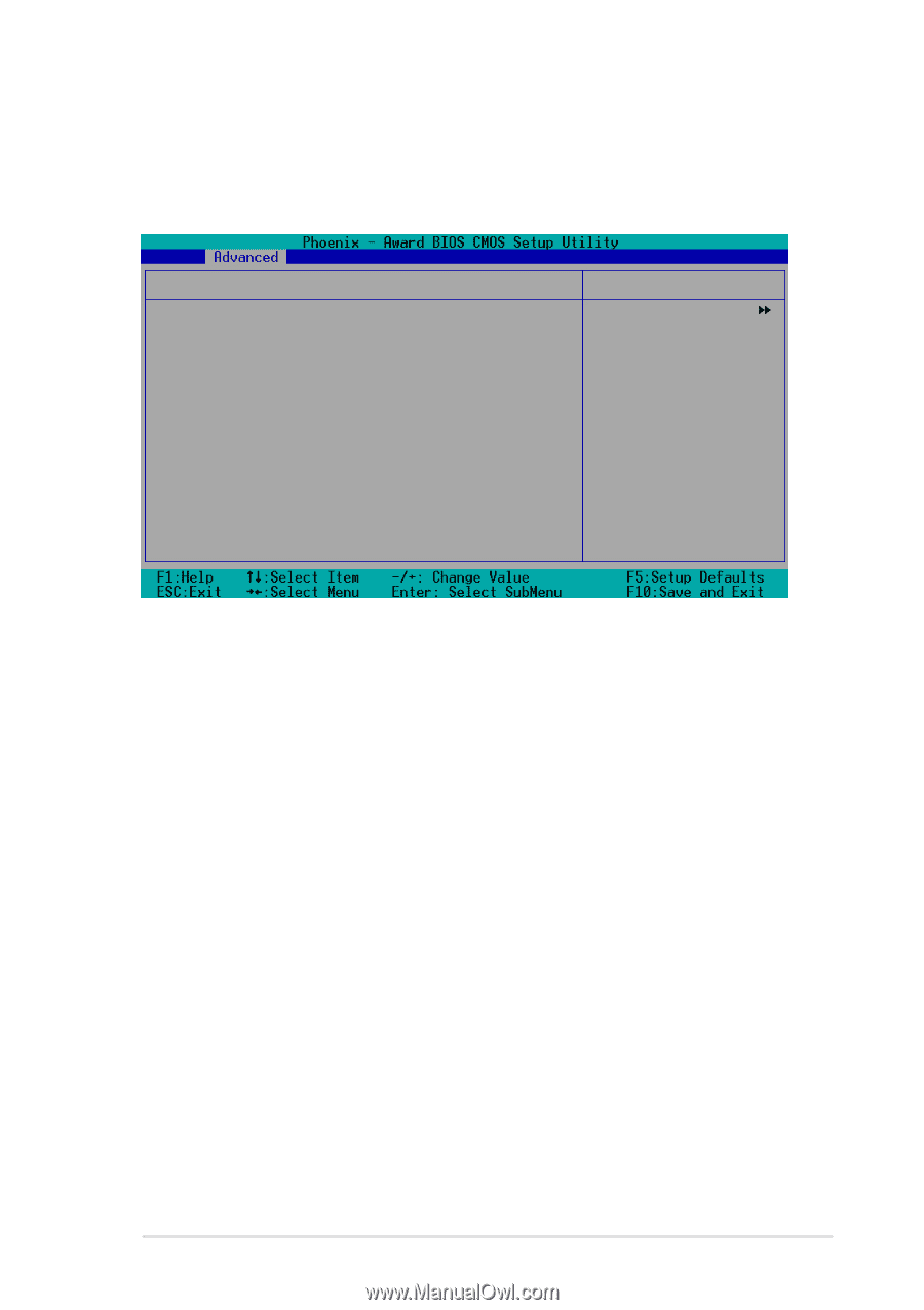
5.4.3 Chipset Configuration The items in this menu show the chipset configuration settings. Select an item then press to display a pop-up menu with the configuration options. Chipset Onboard Video Memory Select Display Device TV_Type TV_Connector Init Display First [32M] [CRT] [NTSC] [CVBS] [PCI slot] Select Menu Item Specific Help Select VGA Share Memory Size Onboard Video Memory [32M] This item allows you to set the memory space reserved for the VGA frame buffer (display memory) within the system main memory. If you have installed a 3D graphics device, select at least 16 MB VGA shared memory size. Note that the more system memory you share with VGA, the less memory space is left for other system devices. Configuration options: [16M] [32M] [64M] Select Display Device [CRT] Allows you to select the primary display device. Configuration options: [CRT] [TV] [CRT+TV] TV_Type [NTSC] Allows you to select the primary TV type. Configuration options: [NTSC] [PAL] [PALM] [PALN] [PALNc] TV_Connector [CVBS] Allows you to select the primary TV connector. Configuration options: [CVBS] [S-Video 0] Init Display First [PCI Slot] Allows you to set which graphics controller to use as the primary boot device. Configuration options: [PCI slot] [AGP] ASUS Terminator 1 C3 barebone system 5-15
-
 1
1 -
2
-
3
-
4
-
5
-
6
-
7
-
8
-
9
-
10
-
11
-
12
-
13
-
14
-
15
-
16
-
17
-
18
-
19
-
20
-
21
-
22
-
23
-
24
-
25
-
26
-
27
-
28
-
29
-
30
-
31
-
32
-
33
-
34
-
35
-
36
-
37
-
38
-
39
-
40
-
41
-
42
-
43
-
44
-
45
-
46
-
47
-
48
-
49
-
50
-
51
-
52
-
53
-
54
-
55
-
56
-
57
-
58
-
59
-
60
-
61
-
62
-
63
-
64
-
65
-
66
-
67
-
68
-
69
-
70
-
71
-
 72
72 -
 73
73 -
 74
74 -
 75
75 -
 76
76 -
 77
77 -
 78
78 -
 79
79 -
 80
80 -
 81
81 -
 82
82 -
83
-
84
-
85
-
86
-
87
-
88
-
89
-
90
-
91
-
92
-
93
-
94
 |
 |