Asus Terminator C3 Terminator C3V User Manual - Page 15
Voltage selector
 |
View all Asus Terminator C3 manuals
Add to My Manuals
Save this manual to your list of manuals |
Page 15 highlights
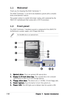
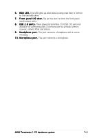
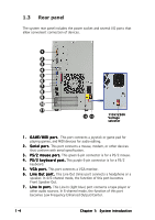
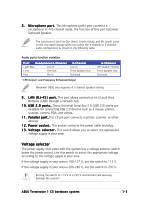
8 . M i c r o p h o n e p o r t . This Microphone (pink) port connects a microphone. In 4/6-channel mode, the function of this port becomes Surround Speaker. The functions of the Line Out (lime), Line In (blue), and Mic (pink) ports on the rear panel change when you select the 4-channel or 6-channel audio configuration as shown in the following table. Audio ports function variation Port Headphone/2-Channel Light Blue Line In Lime Line Out Pink Mic In 4-Channel Line In Front Speaker Out Surround * LFE Output: Low Frequency Enhanced Output 6-Channel LFE Output*/Center Front Speaker Out Surround Windows® 98SE only supports 4.1-channel speaker setting. 9 . L A N ( R J - 4 5 ) p o r t . This port allows connection to a Local Area Network (LAN) through a network hub. 1 0 . U S B 2 . 0 p o r t s . These Universal Serial Bus 2.0 (USB 2.0) ports are available for connecting USB 2.0 devices such as a mouse, printer, scanner, camera, PDA, and others. 1 1 . P a r a l l e l p o r t .This 25-pin port connects a printer, scanner, or other devices. 1 2 . P o w e r s o c k e t . This socket connects the power cable and plug. 1 3 . V o l t a g e s e l e c t o r . This switch allows you to select the appropriate voltage supply in your area. Voltage selector The power supply that came with the system has a voltage selector switch below the power socket. Use this switch to select the appropriate voltage according to the voltage supply in your area. If the voltage supply in your area is 100-127 V, set the switch to 115 V. If the voltage supply in your area is 200-240 V, set the switch to 230 V. Setting the switch to 115 V in a 230 V environment will seriously damage the system! ASUS Terminator 1 C3 barebone system 1-5
-
 1
1 -
2
-
3
-
4
-
5
-
6
-
7
-
8
-
9
-
 10
10 -
 11
11 -
 12
12 -
 13
13 -
 14
14 -
 15
15 -
 16
16 -
 17
17 -
 18
18 -
 19
19 -
 20
20 -
21
-
22
-
23
-
24
-
25
-
26
-
27
-
28
-
29
-
30
-
31
-
32
-
33
-
34
-
35
-
36
-
37
-
38
-
39
-
40
-
41
-
42
-
43
-
44
-
45
-
46
-
47
-
48
-
49
-
50
-
51
-
52
-
53
-
54
-
55
-
56
-
57
-
58
-
59
-
60
-
61
-
62
-
63
-
64
-
65
-
66
-
67
-
68
-
69
-
70
-
71
-
72
-
73
-
74
-
75
-
76
-
77
-
78
-
79
-
80
-
81
-
82
-
83
-
84
-
85
-
86
-
87
-
88
-
89
-
90
-
91
-
92
-
93
-
94
 |
 |
