Asus Terminator C3 Terminator C3V User Manual - Page 16
Internal components
 |
View all Asus Terminator C3 manuals
Add to My Manuals
Save this manual to your list of manuals |
Page 16 highlights
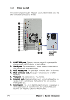
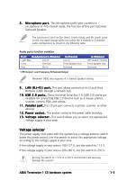
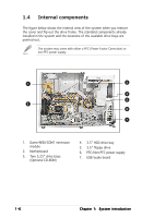
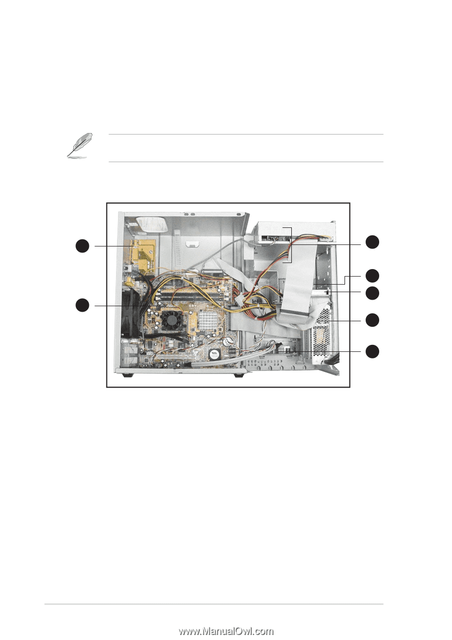
1.4 Internal components The figure below shows the internal view of the system when you remove the cover and flip out the drive frame. The standard components already installed in the system and the locations of the available drive bays are pointed out. The system may come with either a PFC (Power Factor Correction) or non-PFC power supply. 1 3 4 5 2 6 7 1. Game/MIDI/COM1 extension module 2. Motherboard 3. Two 5.25" drive bays (Optional CD-ROM) 4. 3.5" HDD drive bay 5. 3.5" floppy drive 6. PFC/Non-PFC power supply 7. USB/audio board 1-6 Chapter 1: System introduction
-
 1
1 -
2
-
3
-
4
-
5
-
6
-
7
-
8
-
9
-
10
-
 11
11 -
 12
12 -
 13
13 -
 14
14 -
 15
15 -
 16
16 -
 17
17 -
 18
18 -
 19
19 -
 20
20 -
 21
21 -
22
-
23
-
24
-
25
-
26
-
27
-
28
-
29
-
30
-
31
-
32
-
33
-
34
-
35
-
36
-
37
-
38
-
39
-
40
-
41
-
42
-
43
-
44
-
45
-
46
-
47
-
48
-
49
-
50
-
51
-
52
-
53
-
54
-
55
-
56
-
57
-
58
-
59
-
60
-
61
-
62
-
63
-
64
-
65
-
66
-
67
-
68
-
69
-
70
-
71
-
72
-
73
-
74
-
75
-
76
-
77
-
78
-
79
-
80
-
81
-
82
-
83
-
84
-
85
-
86
-
87
-
88
-
89
-
90
-
91
-
92
-
93
-
94
 |
 |
1-6
1-6
1-6
1-6
1-6
Chapter 1:
System introduction
Chapter 1:
System introduction
Chapter 1:
System introduction
Chapter 1:
System introduction
Chapter 1:
System introduction
1.4
Internal components
The figure below shows the internal view of the system when you remove
the cover and flip out the drive frame. The standard components already
installed in the system and the locations of the available drive bays are
pointed out.
The system may come with either a PFC (Power Factor Correction) or
non-PFC power supply.
4.
3.5” HDD drive bay
5.
3.5” floppy drive
6.
PFC/Non-PFC power supply
7.
USB/audio board
1.
Game/MIDI/COM1 extension
module
2.
Motherboard
3.
Two 5.25” drive bays
(Optional CD-ROM)
1
2
3
7
6
4
5