Brother International DB2-B737 Network Users Manual - English - Page 10
Synchronizer, Model, DB2-B737
 |
View all Brother International DB2-B737 manuals
Add to My Manuals
Save this manual to your list of manuals |
Page 10 highlights
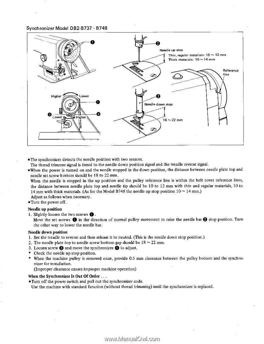
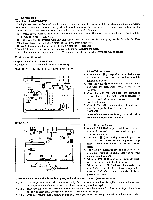
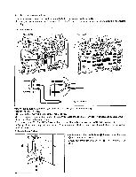
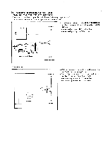
Synchronizer Model DB2-B737 • B748 Higher Lower Lower Higher 0 Needle up stop Thin, regular materials: 10 ^ 12 mm Thick materials: 10 --14 mm Reference line 0 Needle down stop 18 -- 22 mm *The synchronizer detects the needle position with two sensors. The thread trimmer signal is timed to the needle down position signal and the treadle reverse signal. *When the power is turned on and the needle stopped in the down position, the distance between needle plate top and needle set screw bottom should be 18 to 22 mm. When the needle is stopped in the up position and the pulley reference line is within the belt cover reference lines, the distance between needle plate top and needle tip should be 10 to 12 mm with thin and regular materials, 10 to 14 mm with thick materials. (As for the Model B748 the needle up stop position 10 - 14 mm.) Adjust as follows when necessary. *Turn the power off. Needle up position 1. Slightly loosen the two screws 0 . Move the set screws 0 in the direction of normal pulley movement to raise the needle bar 0 stop position. Turn the other way to lower the needle bar. Needle down position 1. Set the treadle to reverse and then release it to neutral. (This is the needle down stop position.) 2. The needle plate top to needle screw bottom gap should be 18 - 22 mm. 3. Loosen screw 0 and move the synchronizer 0 to adjust. * Check the needle up stop position. * When the machine pulley is removed once, provide 0.5 mm clearance between the pulley bottom and the synchro- nizer for installation. (Improper clearance causes improper machine operation) When the Synchronizer Is Out Of Order . . . *Turn off the power switch and pull out the synchronizer code. Use the machine with standard function (without thread trimming) until the synchronizer is replaced.
-
 1
1 -
2
-
3
-
4
-
 5
5 -
 6
6 -
 7
7 -
 8
8 -
 9
9 -
 10
10 -
 11
11 -
 12
12 -
 13
13 -
 14
14 -
 15
15 -
16
-
17
-
18
-
19
-
20
-
21
-
22
-
23
-
24
-
25
-
26
-
27
-
28
-
29
-
30
-
31
-
32
 |
 |