Brother International DB2-B737 Network Users Manual - English - Page 24
®r©
 |
View all Brother International DB2-B737 manuals
Add to My Manuals
Save this manual to your list of manuals |
Page 24 highlights
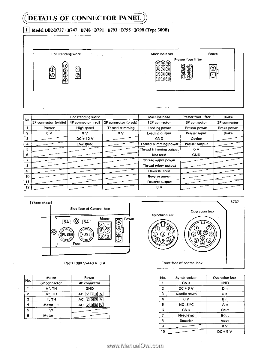
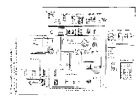
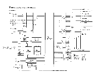
.DETAILS OF CONNECTOR PANEL 1 Model DB2-B737 • B747 • B748 • B791 • B793 • B795 • B798 (Type 3O0B) For standing work O th` 0 CD CD Machine head Presser foot lifter 000 I00© 00® to tt © 0© 00/ Brake No. 2P connector (white) 1 Presser 2 0 V 3 4 5 6 7 8 9 10 11 12 For standing work 4P connector (red) High speed 0 V DC + 12 V Low speed Machine head 2P connector (black) 12P connector Thread trimming Leading power 0 V Leading output GND Thread trimming power Thread trimming output Not used Thread wiper power Thread wiper output Reverse input Reverse power Reverse output 0 V Presser foot lifter 6P connector Presser power Presser input Option Presser output 0 V GND Brake 2P connector Brake power Brake [Three-phase] Side face of Control box 5A 5A FUSE FUSE Fuse Motor Power gi O w Synchronizer Operation box B737 ®r© (Note) 380 V-440 V 3 A Motor No. 6P connector 1 Vf. TH 2 Vf. TH 3 if. TH 4 Motor + 5 Vf 6 Motor - Power 4P connector GND AC M CI CI III AC ©00M Ac El CI 0 El Front face of control box No. Synchronizer 1 GND 2 DC + 5 V 3 Needle down 4 0 V 5 NO. SYC 6 GND 7 Needle up 8 Encoder 9 10 Operation box GND Din Cin Bin Ain Cout Bout Aout 0 V DC + 5 V
-
 1
1 -
2
-
3
-
4
-
5
-
6
-
7
-
8
-
9
-
10
-
11
-
12
-
13
-
14
-
15
-
16
-
17
-
18
-
 19
19 -
 20
20 -
 21
21 -
 22
22 -
 23
23 -
 24
24 -
 25
25 -
 26
26 -
 27
27 -
 28
28 -
 29
29 -
30
-
31
-
32
 |
 |