Brother International DB2-B737 Network Users Manual - English - Page 9
thread trimming
 |
View all Brother International DB2-B737 manuals
Add to My Manuals
Save this manual to your list of manuals |
Page 9 highlights
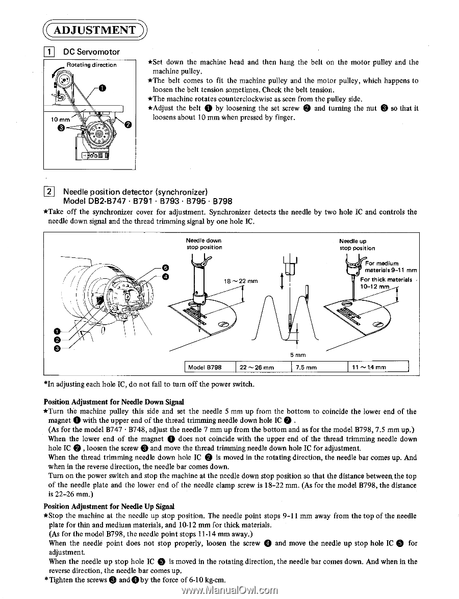
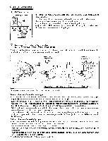
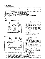
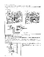
ADJUSTMENT D 1 DC Servomotor Rotating direction 10 mm 0 0 o • • C) 0 ooS *Set down the machine head and then hang the belt on the motor pulley and the machine pulley. *The belt comes to fit the machine pulley and the motor pulley, which happens to loosen the belt tension sometimes. Check the belt tension. *The machine rotates counterclockwise as seen from the pulley side. *Adjust the belt 0 by loosening the set screw 0 and turning the nut 0 so that it loosens about 10 mm when pressed by finger. 2 Needle position detector (synchronizer) Model DB2-B747 • B791 • B793 • B795 • B798 *Take off the synchronizer cover for adjustment. Synchronizer detects the needle by two hole IC and controls the needle down signal and the thread trimming signal by one hole IC. Needle down stop position 0 18 22 mm Needle up stop position 4-eFor medium materials 9-11 mm For thick materials 10-12 mm Nt. 0 0 0 5 mm Model 8798 22'-26 mm 7.5 mm 11 "-1.4 mm *In adjusting each hole IC, do not fail to turn off the power switch. 0 Position Adjustment for Needle Down Signal *Turn the machine pulley this side and set the needle 5 mm up from the bottom to coincide the lower end of the magnet 0 with the upper end of the thread trimming needle down hole IC 0 . (As for the model B747 • B748, adjust the needle 7 mm up from the bottom and as for the model B798, 7.5 mm up.) When the lower end of the magnet does not coincide with the upper end of the thread trimming needle down hole IC 0 , loosen the screw 0 and move the thread trimming needle down hole IC for adjustment. When the thread trimming needle down hole IC 0 is moved in the rotating direction, the needle bar comes up. And when in the reverse direction, the needle bar comes down. Turn on the power switch and stop the machine at the needle down stop position so that the distance between, the top of the needle plate and the lower end of the needle clamp screw is 18-22 mm. (As for the model B798, the distance is 22-26 mm.) Position Adjustment for Needle Up Signal *Stop the machine at the needle up stop position. The needle point stops 9-11 mm away from the top of the needle plate for thin and medium materials, and 10-12 mm for thick materials. (As for the model B798, the needle point stops 11-14 mm away.) When the needle point does not stop properly, loosen the screw 0 and move the needle up stop hole IC 0 for adjustment. When the needle up stop hole IC 0 is moved in the rotating direction, the needle bar comes down. And when in the reverse direction, the needle bar comes up. *Tighten the screws 0 and 0 by the force of 6-10 kg-cm.
-
 1
1 -
2
-
3
-
 4
4 -
 5
5 -
 6
6 -
 7
7 -
 8
8 -
 9
9 -
 10
10 -
 11
11 -
 12
12 -
 13
13 -
 14
14 -
15
-
16
-
17
-
18
-
19
-
20
-
21
-
22
-
23
-
24
-
25
-
26
-
27
-
28
-
29
-
30
-
31
-
32
 |
 |