Brother International DB2-B737 Network Users Manual - English - Page 25
Model, DB2-B738
 |
View all Brother International DB2-B737 manuals
Add to My Manuals
Save this manual to your list of manuals |
Page 25 highlights
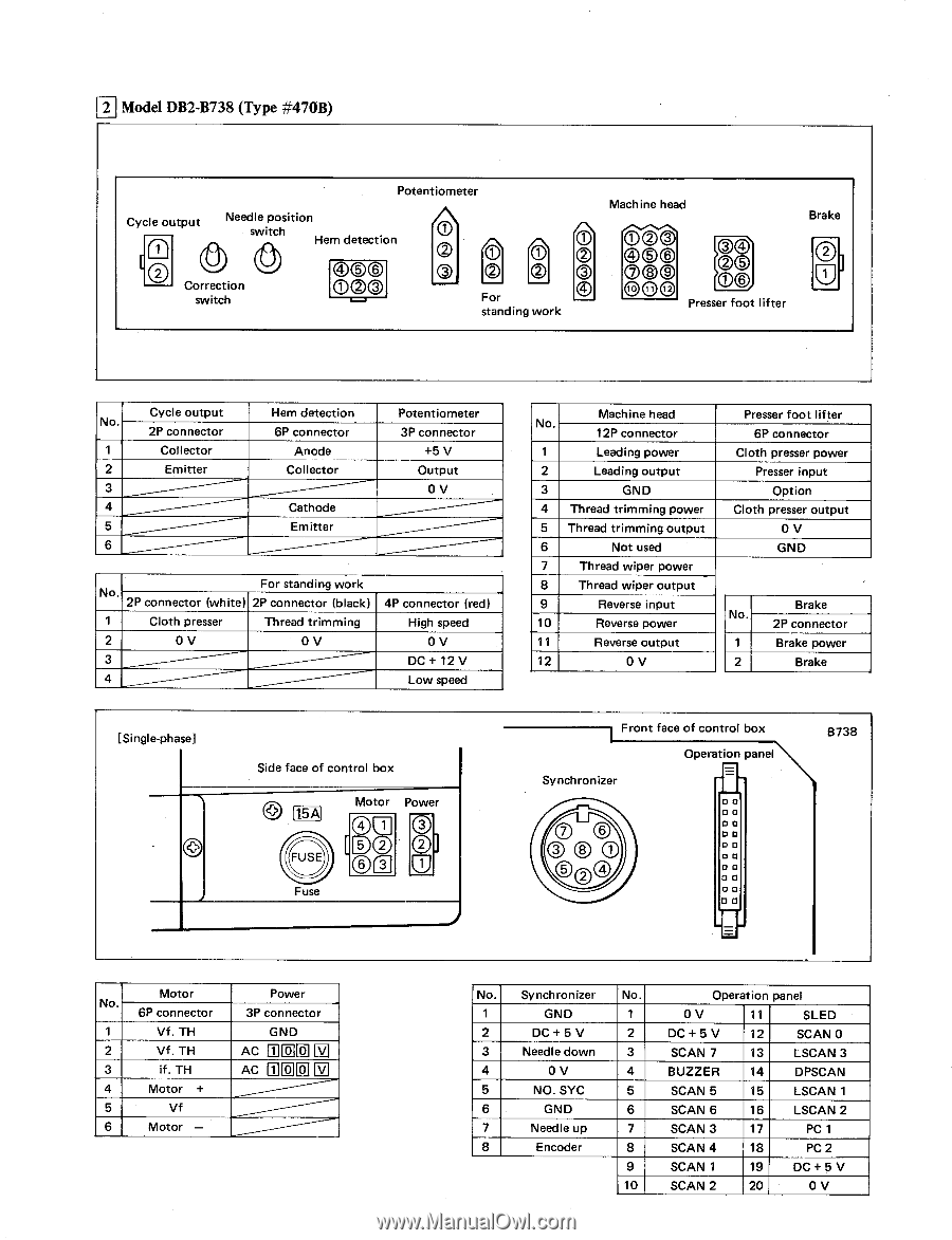
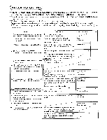
2 Model DB2-B738 (Type #47OB) Potentiometer Cycle output 2 Needle position switch Hem detection O Correction C)SC) 00C) switch ArT\ \Li 0 0 0 For standing work Machine head Brake scp() Presser foot lifter Cycle output No. 2P connector 1 Collector 2 Emitter 3 4 5 6 Hem detection 6P connector Anode Collector Cathode Emitter Potentiometer 3P connector +5 V Output 0V For standing work No. 2P connector (white) 2P connector (black) 1 Cloth presser Thread trimming 2 0V 0V 3 4P connector (red) High speed 0V DC + 12 V Low speed [Single-phase] Side face of control box 15A Motor Power O O Fuse Machine head No. 12P connector 1 Leading power 2 Leading output 3 GND 4 Thread trimming power 5 Thread trimming output 6 Not used 7 Thread wiper power 8 Thread wiper output - 9 Reverse input 10 Reverse power 11 Reverse output 12 0V Presser foot lifter 6P connector Cloth presser power Presser input Option Cloth presser output 0 GND Brake No. 2P connector 1 Brake power 2 Brake Front face of control box Operation panel Synchronizer on O 0 0 0 D 0 D P 0 0 0 CI 8738 Motor No. 6P connector 1 Vf. TH 2 Vf. TH 3 if. TH 4 Motor + 5 Vf 6 Motor - Power 3P connector GND AC il CIO El AC ffl 17 17 V No. Synchronizer No. Operation panel 1 GND 1 0 V 11 SLED 2 DC + 5 V 2 DC + 5 V 12 SCAN 0 3 Needle down 3 SCAN 7 13 LSCAN 3 4 0 V 4 BUZZER 14 DPSCAN 5 NO. SYC 5 SCAN 5 15 LSCAN 1 6 GND 6 SCAN 6 16 LSCAN 2 7 Needle up 7 SCAN 3 17 PC 1 8 Encoder 8 SCAN 4 18 PC 2 9 SCAN 1 19 DC+ 5 V 10 SCAN 2 20 0 V
-
 1
1 -
2
-
3
-
4
-
5
-
6
-
7
-
8
-
9
-
10
-
11
-
12
-
13
-
14
-
15
-
16
-
17
-
18
-
19
-
 20
20 -
 21
21 -
 22
22 -
 23
23 -
 24
24 -
 25
25 -
 26
26 -
 27
27 -
 28
28 -
 29
29 -
 30
30 -
31
-
32
 |
 |