Brother International DB2-B737 Network Users Manual - English - Page 11
short-circuit
 |
View all Brother International DB2-B737 manuals
Add to My Manuals
Save this manual to your list of manuals |
Page 11 highlights
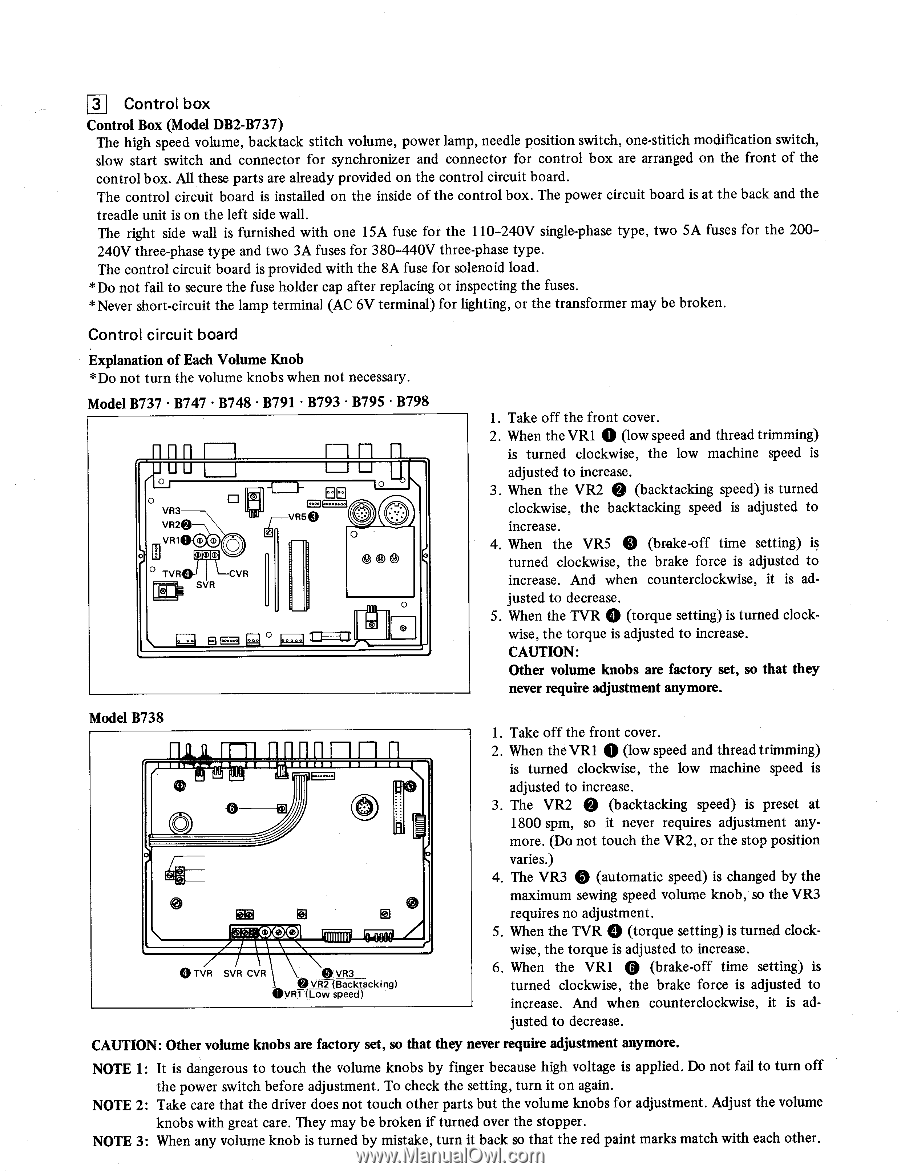
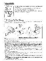
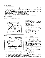
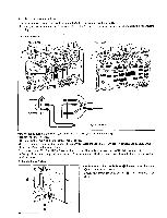
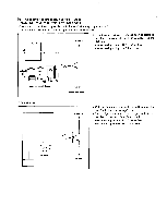
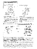
131 Control box Control Box (Model DB2-B737) The high speed volume, backtack stitch volume, power lamp, needle position switch, one-stitich modification switch, slow start switch and connector for synchronizer and connector for control box are arranged on the front of the control box. All these parts are already provided on the control circuit board. The control circuit board is installed on the inside of the control box. The power circuit board is at the back and the treadle unit is on the left side wall. The right side wall is furnished with one 15A fuse for the 110-240V single-phase type, two 5A fuses for the 200240V three-phase type and two 3A fuses for 380-440V three-phase type. The control circuit board is provided with the 8A fuse for solenoid load. *Do not fail to secure the fuse holder cap after replacing or inspecting the fuses. *Never short-circuit the lamp terminal (AC 6V terminal) for lighting, or the transformer may be broken. Control circuit board Explanation of Each Volume Knob *Do not turn the volume knobs when not necessary. Model B737 • B747 • B748 • B791 • B793 • B795 • B798 [-inn r lu 0 VR3 VR2 nn 11 E L_I LJ 0 I- BEI L vR50 VR1O (1) O mimiml ° TvRal I LCVR SVR O 0 0 1=1 0 0 1. Take off the front cover. 2. When the VR1 0 (low speed and thread trimming) is turned clockwise, the low machine speed is adjusted to increase. 3. When the VR2 0 (backtacking speed) is turned clockwise, the backtacking speed is adjusted to increase. 4. When the VR5 0 (brake-off time setting) is turned clockwise, the brake force is adjusted to increase. And when counterclockwise, it is ad- justed to decrease. 5. When the TVR 0 (torque setting) is turned clock- wise, the torque is adjusted to increase. CAUTION: Other volume knobs are factory set, so that they never require adjustment anymore. Model B738 == 0 1. Take off the front cover. 2. When the VR1 0 (low speed and thread trimming) is turned clockwise, the low machine speed is adjusted to increase. 3. The VR2 0 (backtacking speed) is preset at 1800 spm, so it never requires adjustment anymore. (Do not touch the VR2, or the stop position 0 a) 0 0 0 TVR SVR CVR 0 VR3 VR2 (Backtacking) UVR1 (Low speed) 0 varies.) 4. The VR3 0 (automatic speed) is changed by the maximum sewing speed volume knob, so the VR3 requires no adjustment. 5. When the TVR (torque setting) is turned clockwise, the torque is adjusted to increase. 6. When the VR1 0 (brake-off time setting) is turned clockwise, the brake force is adjusted to increase. And when counterclockwise, it is adjusted to decrease. CAUTION: Other volume knobs are factory set, so that they never require adjustment anymore. NOTE 1: It is dangerous to touch the volume knobs by finger because high voltage is applied. Do not fail to turn off the power switch before adjustment. To check the setting, turn it on again. NOTE 2: Take care that the driver does not touch other parts but the volume knobs for adjustment. Adjust the volume knobs with great care. They may be broken if turned over the stopper. NOTE 3: When any volume knob is turned by mistake, turn it back so that the red paint marks match with each other.
-
 1
1 -
2
-
3
-
4
-
5
-
 6
6 -
 7
7 -
 8
8 -
 9
9 -
 10
10 -
 11
11 -
 12
12 -
 13
13 -
 14
14 -
 15
15 -
 16
16 -
17
-
18
-
19
-
20
-
21
-
22
-
23
-
24
-
25
-
26
-
27
-
28
-
29
-
30
-
31
-
32
 |
 |