Brother International DB2-B737 Network Users Manual - English - Page 28
Checking, Machine, Solenoids
 |
View all Brother International DB2-B737 manuals
Add to My Manuals
Save this manual to your list of manuals |
Page 28 highlights
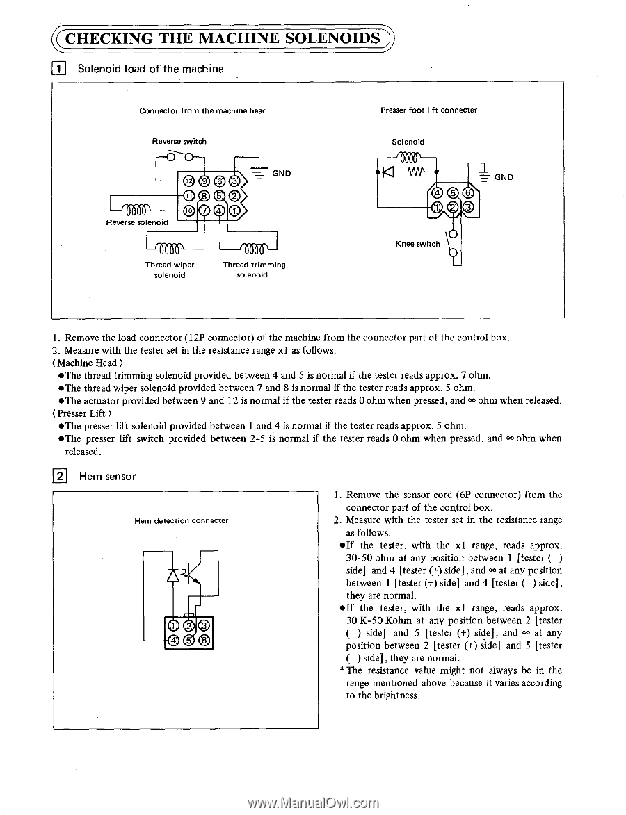
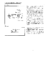
CHECKING THE MACHINE SOLENOIDS 11 Solenoid load of the machine Connector from the machine head Reverse switch Reverse solenoid 12 9 3 0 8 5 10 7 GND Thread wiper solenoid Thread trimming solenoid Presser foot lift connecter Solenoid GND 4 6 1 Knee switch 1. Remove the load connector (12P connector) of the machine from the connector part of the control box. 2. Measure with the tester set in the resistance range xl as follows. ( Machine Head ) •The thread trimming solenoid provided between 4 and 5 is normal if the tester reads approx. 7 ohm. •The thread wiper solenoid provided between 7 and 8 is normal if the tester reads approx. 5 ohm. •The actuator provided between 9 and 12 is normal if the tester reads 0 ohm when pressed, and OO ohm when released. ( Presser Lift ) •The presser lift solenoid provided between 1 and 4 is normal if the tester reads approx. 5 ohm. •The presser lift switch provided between 2-5 is normal if the tester reads 0 ohm when pressed, and OO ohm when released. 2 Hem sensor Hem detection connecter 1 20 4 5 1. Remove the sensor cord (6P connector) from the connector part of the control box. 2. Measure with the tester set in the resistance range as follows. •If the tester, with the x1 range, reads approx. 30-50 ohm at any position between 1 [tester (-) side] and 4 [tester (+) side] , and °C3 at any position between 1 [tester (+) side] and 4 [tester (-) side], they are normal. •If the tester, with the xl range, reads approx. 30 K-50 Kohm at any position between 2 [tester (-) side] and 5 [tester (+) side], and OO at any position between 2 [tester (+) side] and 5 [tester (-) side] , they are normal. * The resistance value might not always be in the range mentioned above because it varies according to the brightness.
-
 1
1 -
2
-
3
-
4
-
5
-
6
-
7
-
8
-
9
-
10
-
11
-
12
-
13
-
14
-
15
-
16
-
17
-
18
-
19
-
20
-
21
-
22
-
 23
23 -
 24
24 -
 25
25 -
 26
26 -
 27
27 -
 28
28 -
 29
29 -
 30
30 -
 31
31 -
 32
32
 |
 |