Brother International DB2-B737 Network Users Manual - English - Page 12
Treadle, Brush, replacement
 |
View all Brother International DB2-B737 manuals
Add to My Manuals
Save this manual to your list of manuals |
Page 12 highlights
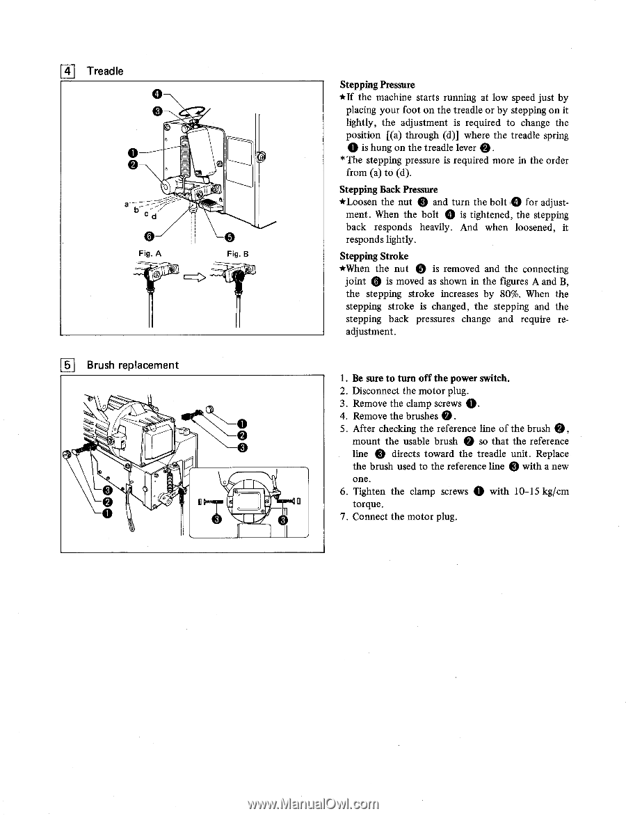
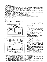
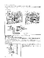
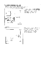
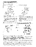
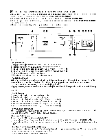
4 Treadle C2i OJ Fig. A Fig. B 151 Brush replacement 0 a O O ..; 0 Stepping Pressure *If the machine starts running at low speed just by placing your foot on the treadle or by stepping on it lightly, the adjustment is required to change the position [(a) through (d)] where the treadle spring is hung on the treadle lever 0 * The stepping pressure is required more in the order from (a) to (d). Stepping Back Pressure *Loosen the nut Q and turn the bolt 0 for adjust- ment. When the bolt 0 is tightened, the stepping back responds heavily. And when loosened, it responds lightly. Stepping Stroke *When the nut 0 is removed and the connecting joint Q is moved as shown in the figures A and B, the stepping stroke increases by 80%. When the stepping stroke is changed, the stepping and the stepping back pressures change and require readjustment. 1. Be sure to turn off the power switch. 2. Disconnect the motor plug. 3. Remove the clamp screws 0. 4. Remove the brushes 0 . 5. After checking the reference line of the brush 0, mount the usable brush 0 so that the reference line e directs toward the treadle unit. Replace the brush used to the reference line Q with a new one. 6. Tighten the clamp screws 0 with 10-15 kg/cm torque. 7. Connect the motor plug. .
-
 1
1 -
2
-
3
-
4
-
5
-
6
-
 7
7 -
 8
8 -
 9
9 -
 10
10 -
 11
11 -
 12
12 -
 13
13 -
 14
14 -
 15
15 -
 16
16 -
 17
17 -
18
-
19
-
20
-
21
-
22
-
23
-
24
-
25
-
26
-
27
-
28
-
29
-
30
-
31
-
32
 |
 |