Brother International DB2-B737 Network Users Manual - English - Page 2
Introduction, Table, Contents
 |
View all Brother International DB2-B737 manuals
Add to My Manuals
Save this manual to your list of manuals |
Page 2 highlights
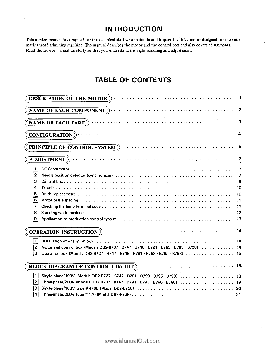
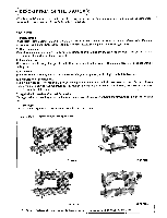
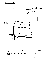
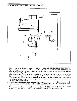
INTRODUCTION This service manual is compiled for the technical staff who maintain and inspect the drive motor designed for the automatic thread trimming machine. The manual describes the motor and the control box and also covers adjustments. Read the service manual carefully so that you understand the right handling and adjustment. TABLE OF CONTENTS 0:IESCRIPTION OF THE MOTOR4 1 ((NAME OF EACH COMPONENT 2 (NAME OF EACH PART) 3 .CONFIGURATION; 4 (PRINCIPLE OF CONTROL SYSTEM) 5 1-ADJUSTMENT 7 DC Servomotor 7 I i Needle position detector (synchronizer) 7 r31 C•ontrol box 9 T• readle 10 O Brush replacement 10 lel Motor brake spacing 11 pi Checking the lamp terminal code 11 Standing work machine 12 pi Application to production control system 13 ((OPERATION INSTRUCTION 14 Installation of operation box 14 M Motor and control box (Models DB2-B737 • B747 • B748 • B791 • B793 • B795 • B798) 14 0 Operation box (Models DB2-B737 • B747 • B748 • B791 • B793 • B795 • B798) 15 ((BLOCK DIAGRAM OF CONTROL CIRCUIT) 18 Ii i Single-phase/100V (Models DB2-6737 • B747 • B791 • B793 • B795 • B798) 18 E Three-phase/200V (Models DB2-B737 • B747 • B791 • B793 • B795 • B798) 19 pi S•ingle-phase/100V type #470B (Model DB2-8738) 20 E Three-phase/200V type #470 (Model DB2-8738) 21
-
 1
1 -
 2
2 -
 3
3 -
 4
4 -
 5
5 -
 6
6 -
 7
7 -
 8
8 -
9
-
10
-
11
-
12
-
13
-
14
-
15
-
16
-
17
-
18
-
19
-
20
-
21
-
22
-
23
-
24
-
25
-
26
-
27
-
28
-
29
-
30
-
31
-
32
 |
 |