Brother International GT-381 Instruction Manual - English - Page 128
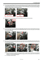
Positioning Pin, Flat Spring, Print Head, Slide the Print Head into the Fl
 |
View all Brother International GT-381 manuals
Add to My Manuals
Save this manual to your list of manuals |
Page 128 highlights
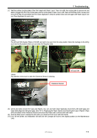
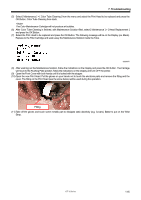
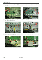
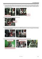
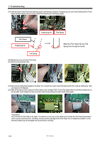
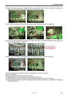
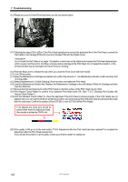
7. Troubleshooting (19) Hold the knob of the Print Head (left) and push it downward so that the V-shaped groove can fit the Positioning Pin. Push down the Print Head to fix the corner of the Print Head by the Flat Spring (right). Print Head Positioning Pin Positioning Pin Flat Spring Slide the Print Head into the Flat Spring from the right to the left. Flat Spring (20) Rotate the Lever to fix the Print Head. (21) Remove the protection film. (22) Remove the Fitting that inserted in the step (15), connect the Tube to the Print Head and fix the Tube by rotating the Tube Connector by 90 degrees. (23) Take off the gloves and connect the Flat Cable to the Carriage PCB. Put the Flat Cable with the terminal (metal) side on the top (left), insert straight into the connector and fix it by pushing the tabs of both sides (right). Do not insert the Flat Cable at an angle. The electric current may not be stable and increase the Print Head temperature. which causes machine errors, mis-firing, and give serious damage to the Print Head. Do not repeat the insertion, or the terminal (metal) may be damaged and cause serious mis-firing. 118 GT-3 Series
-
 1
1 -
2
-
3
-
4
-
5
-
6
-
7
-
8
-
9
-
10
-
11
-
12
-
13
-
14
-
15
-
16
-
17
-
18
-
19
-
20
-
21
-
22
-
23
-
24
-
25
-
26
-
27
-
28
-
29
-
30
-
31
-
32
-
33
-
34
-
35
-
36
-
37
-
38
-
39
-
40
-
41
-
42
-
43
-
44
-
45
-
46
-
47
-
48
-
49
-
50
-
51
-
52
-
53
-
54
-
55
-
56
-
57
-
58
-
59
-
60
-
61
-
62
-
63
-
64
-
65
-
66
-
67
-
68
-
69
-
70
-
71
-
72
-
73
-
74
-
75
-
76
-
77
-
78
-
79
-
80
-
81
-
82
-
83
-
84
-
85
-
86
-
87
-
88
-
89
-
90
-
91
-
92
-
93
-
94
-
95
-
96
-
97
-
98
-
99
-
100
-
101
-
102
-
103
-
104
-
105
-
106
-
107
-
108
-
109
-
110
-
111
-
112
-
113
-
114
-
115
-
116
-
117
-
118
-
119
-
120
-
121
-
122
-
 123
123 -
 124
124 -
 125
125 -
 126
126 -
 127
127 -
 128
128 -
 129
129 -
 130
130 -
 131
131 -
 132
132 -
 133
133 -
134
-
135
-
136
-
137
-
138
-
139
-
140
-
141
-
142
-
143
-
144
-
145
-
146
-
147
-
148
 |
 |
