Cisco 5510 Getting Started Guide - Page 18
Balancing Traffic to Maximize Throughput
 |
UPC - 882658094767
View all Cisco 5510 manuals
Add to My Manuals
Save this manual to your list of manuals |
Page 18 highlights
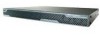
Balancing Traffic to Maximize Throughput Chapter 2 Maximizing Throughput on the ASA 5550 Note To establish fiber connectivity on the adaptive security appliance, you must order and install SFP modules for each fiber port you want to use. For more information on fiber ports and SFP modules, see the "Installing SFP Modules" section on page 3-6. Figure 2-1 shows the embedded ports on the Cisco ASA 5550. Figure 2-1 Embedded Ports on the ASA 5550 Slot 1 Slot 0 CONSOLE AUX MGMT USB2 USB1 PWR STATUS 153217 LNK 3 2 1 0 SPD Ethernet Fiber FLASH LINK SPD LINK SPD LINK SPD LINK SPD 3 2 1 0 POWER STATUS ACTIVE VPN FLASH Ethernet Note Although Slot 1 has four copper Ethernet ports and four fiber Ethernet ports, you can use only four Slot 1 ports at a time. For example, you could use two Slot 1 copper ports and two fiber ports, but you cannot use fiber ports if you are already using all four Slot 1 copper ports. Balancing Traffic to Maximize Throughput To maximize traffic throughput, configure the adaptive security appliance so that traffic is distributed equally between the two buses in the device. To achieve this, lay out the network so that all traffic flows through both Bus 0 (Slot 0) and Bus 1 (Slot 1), entering through one bus and exiting through the other. Cisco ASA 5500 Series Getting Started Guide 2-2 78-19186-01
-
 1
1 -
2
-
3
-
4
-
5
-
6
-
7
-
8
-
9
-
10
-
11
-
12
-
 13
13 -
 14
14 -
 15
15 -
 16
16 -
 17
17 -
 18
18 -
 19
19 -
 20
20 -
 21
21 -
 22
22 -
 23
23 -
24
-
25
-
26
-
27
-
28
-
29
-
30
-
31
-
32
-
33
-
34
-
35
-
36
-
37
-
38
-
39
-
40
-
41
-
42
-
43
-
44
-
45
-
46
-
47
-
48
-
49
-
50
-
51
-
52
-
53
-
54
-
55
-
56
-
57
-
58
-
59
-
60
-
61
-
62
-
63
-
64
-
65
-
66
-
67
-
68
-
69
-
70
-
71
-
72
-
73
-
74
-
75
-
76
-
77
-
78
-
79
-
80
-
81
-
82
-
83
-
84
-
85
-
86
-
87
-
88
-
89
-
90
-
91
-
92
-
93
-
94
-
95
-
96
-
97
-
98
-
99
-
100
-
101
-
102
-
103
-
104
-
105
-
106
-
107
-
108
-
109
-
110
-
111
-
112
-
113
-
114
-
115
-
116
-
117
-
118
-
119
-
120
-
121
-
122
-
123
-
124
-
125
-
126
-
127
-
128
-
129
-
130
-
131
-
132
-
133
-
134
-
135
-
136
-
137
-
138
-
139
-
140
-
141
-
142
-
143
-
144
-
145
-
146
-
147
-
148
-
149
-
150
-
151
-
152
-
153
-
154
-
155
-
156
-
157
-
158
-
159
-
160
-
161
-
162
-
163
-
164
-
165
-
166
-
167
-
168
-
169
-
170
-
171
-
172
-
173
-
174
-
175
-
176
-
177
-
178
-
179
-
180
-
181
-
182
-
183
-
184
-
185
-
186
-
187
-
188
-
189
-
190
-
191
-
192
-
193
-
194
-
195
-
196
-
197
-
198
-
199
-
200
-
201
-
202
-
203
-
204
-
205
-
206
-
207
-
208
 |
 |
