Cisco 5510 Getting Started Guide - Page 48
Rack-Mounting the Chassis, Step 1
 |
UPC - 882658094767
View all Cisco 5510 manuals
Add to My Manuals
Save this manual to your list of manuals |
Page 48 highlights
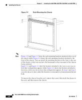
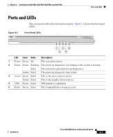
Installing the Chassis Chapter 4 Installing the ASA 5500, ASA 5510, ASA 5520, and ASA 5540 Figure 4-4 Rack-Mounting the Chassis POWER STATUS ACTIVE VPN FLASH CISCOAAdaSpAtiv5e 5S4ec0urSitEyRAIEpSpliance 119633 Note Figure 4-2 and Figure 4-3 show the rack mounting brackets attached to the rear of the chassis while Figure 4-4 shows the rack mounting brackets attached to the front of the chassis. You can attach the mounting brackets to the front or the rear of the chassis so that you can have the front panel or the rear panel of the chassis facing outward. Figure 4-2 and Figure 4-3 show the brackets attached to the rear so you can see how that configuration appears while Figure 4-4 shows the brackets attached to the front so that you can see how that configuration appears. In Step 1 and Step 2, you will choose to have either the brackets rear mounted or front mounted but not both. To remove the chassis from the rack, remove the screws that attach the chassis to the rack, and then remove the chassis. Cisco ASA 5500 Series Getting Started Guide 4-6 78-19186-01
-
 1
1 -
2
-
3
-
4
-
5
-
6
-
7
-
8
-
9
-
10
-
11
-
12
-
13
-
14
-
15
-
16
-
17
-
18
-
19
-
20
-
21
-
22
-
23
-
24
-
25
-
26
-
27
-
28
-
29
-
30
-
31
-
32
-
33
-
34
-
35
-
36
-
37
-
38
-
39
-
40
-
41
-
42
-
 43
43 -
 44
44 -
 45
45 -
 46
46 -
 47
47 -
 48
48 -
 49
49 -
 50
50 -
 51
51 -
 52
52 -
 53
53 -
54
-
55
-
56
-
57
-
58
-
59
-
60
-
61
-
62
-
63
-
64
-
65
-
66
-
67
-
68
-
69
-
70
-
71
-
72
-
73
-
74
-
75
-
76
-
77
-
78
-
79
-
80
-
81
-
82
-
83
-
84
-
85
-
86
-
87
-
88
-
89
-
90
-
91
-
92
-
93
-
94
-
95
-
96
-
97
-
98
-
99
-
100
-
101
-
102
-
103
-
104
-
105
-
106
-
107
-
108
-
109
-
110
-
111
-
112
-
113
-
114
-
115
-
116
-
117
-
118
-
119
-
120
-
121
-
122
-
123
-
124
-
125
-
126
-
127
-
128
-
129
-
130
-
131
-
132
-
133
-
134
-
135
-
136
-
137
-
138
-
139
-
140
-
141
-
142
-
143
-
144
-
145
-
146
-
147
-
148
-
149
-
150
-
151
-
152
-
153
-
154
-
155
-
156
-
157
-
158
-
159
-
160
-
161
-
162
-
163
-
164
-
165
-
166
-
167
-
168
-
169
-
170
-
171
-
172
-
173
-
174
-
175
-
176
-
177
-
178
-
179
-
180
-
181
-
182
-
183
-
184
-
185
-
186
-
187
-
188
-
189
-
190
-
191
-
192
-
193
-
194
-
195
-
196
-
197
-
198
-
199
-
200
-
201
-
202
-
203
-
204
-
205
-
206
-
207
-
208
 |
 |
