Cisco 5510 Getting Started Guide - Page 41
Connecting the LC Connector, Step 7 - series router
 |
UPC - 882658094767
View all Cisco 5510 manuals
Add to My Manuals
Save this manual to your list of manuals |
Page 41 highlights
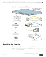
Chapter 3 Installing the ASA 5550 Figure 3-15 Connecting the LC Connector LNK 3 2 1 Cisco SSM-4GE 0 SPD 2 1 POWER STATUS 153214 MMGGMMTT UUSSBB22 USB1 What to Do Next 1 LC connector 2 SFP module Step 7 Step 8 c. Connect the other end of the cable to a network device, such as a router, switch, or hub. Connect the power cord to the adaptive security appliance and plug the other end to the power source. Power on the chassis. What to Do Next Continue with Chapter 7, "Configuring the Adaptive Security Appliance." 78-19186-01 Cisco ASA 5500 Series Getting Started Guide 3-19
-
 1
1 -
2
-
3
-
4
-
5
-
6
-
7
-
8
-
9
-
10
-
11
-
12
-
13
-
14
-
15
-
16
-
17
-
18
-
19
-
20
-
21
-
22
-
23
-
24
-
25
-
26
-
27
-
28
-
29
-
30
-
31
-
32
-
33
-
34
-
35
-
 36
36 -
 37
37 -
 38
38 -
 39
39 -
 40
40 -
 41
41 -
 42
42 -
 43
43 -
 44
44 -
 45
45 -
 46
46 -
47
-
48
-
49
-
50
-
51
-
52
-
53
-
54
-
55
-
56
-
57
-
58
-
59
-
60
-
61
-
62
-
63
-
64
-
65
-
66
-
67
-
68
-
69
-
70
-
71
-
72
-
73
-
74
-
75
-
76
-
77
-
78
-
79
-
80
-
81
-
82
-
83
-
84
-
85
-
86
-
87
-
88
-
89
-
90
-
91
-
92
-
93
-
94
-
95
-
96
-
97
-
98
-
99
-
100
-
101
-
102
-
103
-
104
-
105
-
106
-
107
-
108
-
109
-
110
-
111
-
112
-
113
-
114
-
115
-
116
-
117
-
118
-
119
-
120
-
121
-
122
-
123
-
124
-
125
-
126
-
127
-
128
-
129
-
130
-
131
-
132
-
133
-
134
-
135
-
136
-
137
-
138
-
139
-
140
-
141
-
142
-
143
-
144
-
145
-
146
-
147
-
148
-
149
-
150
-
151
-
152
-
153
-
154
-
155
-
156
-
157
-
158
-
159
-
160
-
161
-
162
-
163
-
164
-
165
-
166
-
167
-
168
-
169
-
170
-
171
-
172
-
173
-
174
-
175
-
176
-
177
-
178
-
179
-
180
-
181
-
182
-
183
-
184
-
185
-
186
-
187
-
188
-
189
-
190
-
191
-
192
-
193
-
194
-
195
-
196
-
197
-
198
-
199
-
200
-
201
-
202
-
203
-
204
-
205
-
206
-
207
-
208
 |
 |

3-19
Cisco ASA 5500 Series Getting Started Guide
78-19186-01
Chapter 3
Installing the ASA 5550
What to Do Next
Figure 3-15
Connecting the LC Connector
c.
Connect the other end of the cable to a network device, such as a router,
switch, or hub.
Step 7
Connect the power cord to the adaptive security appliance and plug the other end
to the power source.
Step 8
Power on the chassis.
What to Do Next
Continue with
Chapter 7, “Configuring the Adaptive Security Appliance.”
1
LC connector
2
SFP module
MGMT
USB2
Cisco SSM-4GE
LNK
SPD
0
1
2
3
MGMT
USB2
USB1
POWER
STATUS
1
153214
2