Cisco 7609-S Installation Guide - Page 29
Load Sharing - power consumption
 |
View all Cisco 7609-S manuals
Add to My Manuals
Save this manual to your list of manuals |
Page 29 highlights
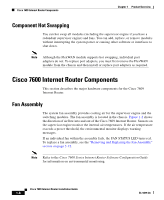
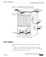
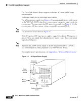
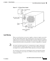
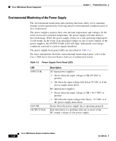
Chapter 1 Product Overview Cisco 7600 Internet Router Components Figure 1-4 DC-Input Power Supply Terminal block cover 16028 DC power cable terminal block Power switch I 0 INPUT FAN OUTPUT OK OK FAIL Status LEDs Captive installation screw Load Sharing When you install and turn on two power supplies, each power supply concurrently provides approximately half of the required power to the system. If one power supply fails, the second power supply immediately assumes full power to maintain uninterrupted system operation. Installing the second power supply enables load sharing and fault tolerance automatically; no software configuration is required. Note For proper load-sharing operation in a redundant power supply configuration, you must install two modules in the chassis. If you fail to install two modules, you might receive spurious OUTPUT FAIL indications on the power supply. For information about the power management feature and individual module power consumption, refer to the Cisco 7600 Series Internet Router Software Configuration Guide. OL-5079-04 Cisco 7609 Internet Router Installation Guide 1-11
-
 1
1 -
2
-
3
-
4
-
5
-
6
-
7
-
8
-
9
-
10
-
11
-
12
-
13
-
14
-
15
-
16
-
17
-
18
-
19
-
20
-
21
-
22
-
23
-
 24
24 -
 25
25 -
 26
26 -
 27
27 -
 28
28 -
 29
29 -
 30
30 -
 31
31 -
 32
32 -
 33
33 -
 34
34 -
35
-
36
-
37
-
38
-
39
-
40
-
41
-
42
-
43
-
44
-
45
-
46
-
47
-
48
-
49
-
50
-
51
-
52
-
53
-
54
-
55
-
56
-
57
-
58
-
59
-
60
-
61
-
62
-
63
-
64
-
65
-
66
-
67
-
68
-
69
-
70
-
71
-
72
-
73
-
74
-
75
-
76
-
77
-
78
-
79
-
80
-
81
-
82
-
83
-
84
-
85
-
86
-
87
-
88
-
89
-
90
-
91
-
92
-
93
-
94
-
95
-
96
-
97
-
98
-
99
-
100
-
101
-
102
-
103
-
104
-
105
-
106
-
107
-
108
-
109
-
110
-
111
-
112
-
113
-
114
-
115
-
116
-
117
-
118
-
119
-
120
 |
 |
